Nissan Frontier D22. Manual - part 479


  Index      Nissan     Nissan Frontier D22 Pickup (1998-2004 year) - Service and Repair Manual


Search            


Content   ..  477  478  479  480   ..


Nissan Frontier D22. Manual - part 479


DTC P1144, P1164 HO2S1

EC-1019

[VG33E]

C

D

E

F

G

H

I

J

K

L

M

A

EC

6. 

CHECK HEATED OXYGEN SENSOR 1

With CONSULT-II

1.

Start engine and warm it up to normal operating temperature.

2.

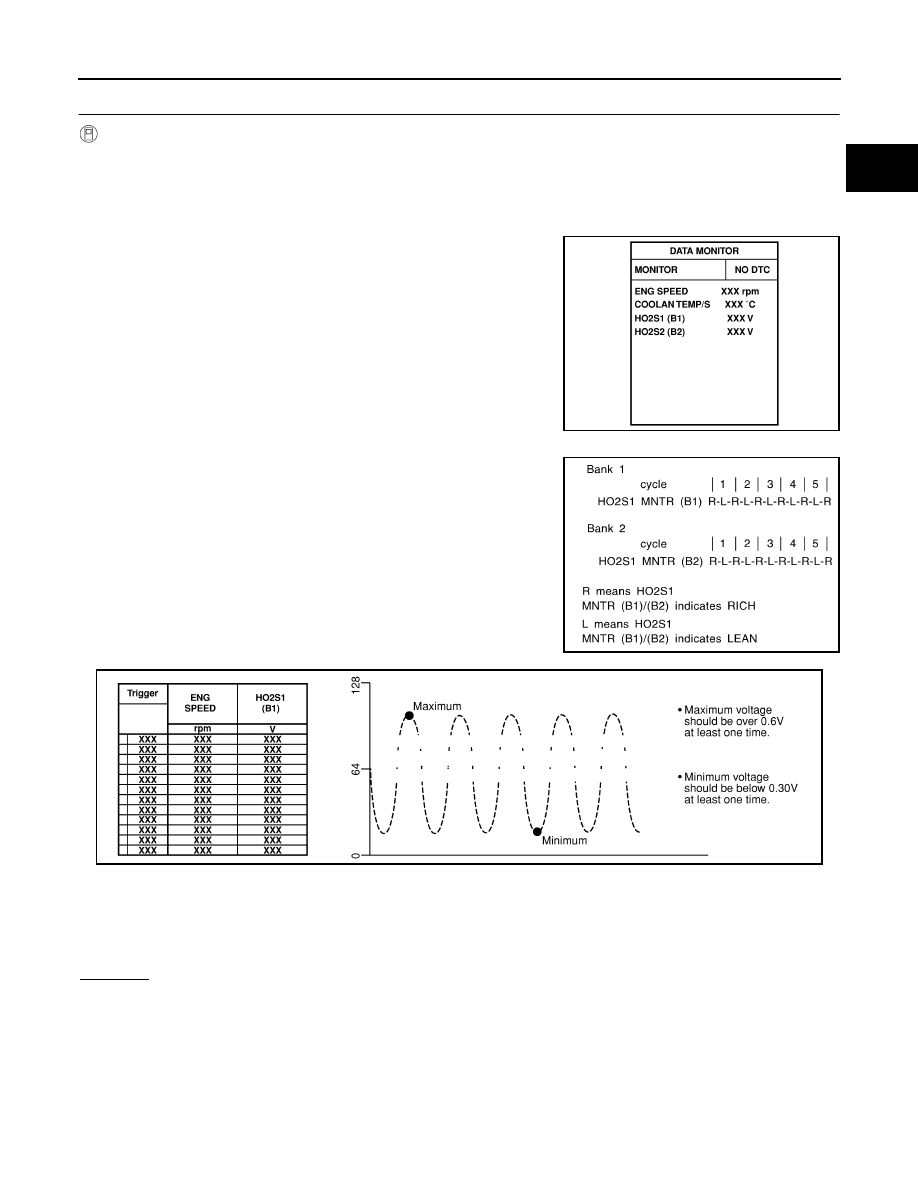
Select  “MANU TRIG” in “DATA MONITOR” mode with CONSULT-II, and select “HO2S1 (B1)/(B2)” and
“HO2S1 MNTR (B1)/(B2)”.

3.

Hold engine speed at 2,000 rpm under no load during the following steps.

4.

Touch “RECORD” on CONSULT-II screen.

5.

Check the following.

“HO2S1 MNTR (B1)/(B2)” in “DATA MONITOR” mode changes
from “RICH” to “LEAN” to “RICH” more than 5 times in 10 sec-
onds.
5 times (cycles) are counted as shown below.

“HO2S1 (B1)/(B2)” voltage goes above 0.6V at least once.

“HO2S1 (B1)/(B2)” voltage goes below 0.3V at least once.

“HO2S1 (B1)/(B2)” voltage never exceeds 1.0V.

CAUTION:

Discard any heated oxygen sensor which has been dropped from a height of more than 0.5 m (19.7
in) onto a hard surface such as a concrete floor; use a new one.

Before installing new oxygen sensor, clean exhaust system threads using Oxygen Sensor Thread
Cleaner tool J-43897-18 or J-43897-12 and approved anti-seize lubricant.

OK or NG

OK

>> GO TO 8.

NG

>> Replace malfunctioning heated oxygen sensor 1.

SEF967Y

SEF647Y

SEF648Y

EC-1020

[VG33E]

DTC P1144, P1164 HO2S1

7. 

CHECK HEATED OXYGEN SENSOR 1

 Without CONSULT-II

1.

Start engine and warm it up to normal operating temperature.

2.

Set voltmeter probes between ECM terminal 50 (bank 1 signal)
or 51 (bank 2 signal) and engine ground.

3.

Check the following with engine speed held at 2,000 rpm con-
stant under no load.

The voltage fluctuates between 0 to 0.3V and 0.6 to 1.0V more
than 5 times within 10 seconds.

The maximum voltage is over 0.6V at least 1 time.

The minimum voltage is below 0.3V at least 1 time.

The voltage never exceeds 1.0V.

1 time: 0 - 0.3V 

→ 0.6 - 1.0V → 0 - 0.3V

2 times: 0 - 0.3V 

→ 0.6 - 1.0V → 0 - 0.3V → 0.6 - 1.0V → 0 - 0.3V

CAUTION:

Discard any heated oxygen sensor which has been dropped from a height of more than 0.5 m (19.7
in) onto a hard surface such as a concrete floor; use a new one.

Before installing new oxygen sensor, clean exhaust system threads using Oxygen Sensor Thread
Cleaner tool J-43897-18 or J-43897-12 and approved anti-seize lubricant.

OK or NG

OK

>> GO TO 8.

NG

>> Replace malfunctioning heated oxygen sensor 1.

8. 

CHECK INTERMITTENT INCIDENT

Refer to 

EC-696, "TROUBLE DIAGNOSIS FOR INTERMITTENT INCIDENT"

 .

For circuit, refer to  

EC-770, "Wiring Diagram"

 .

>> INSPECTION END.

Removal and Installation

UBS00DNC

HEATED OXYGEN SENSOR 1

Refer to 

EM-80, "OUTER COMPONENT PARTS"

 .

PBIB2157E

DTC P1146, P1166 HO2S2

EC-1021

[VG33E]

C

D

E

F

G

H

I

J

K

L

M

A

EC

DTC P1146, P1166 HO2S2

PFP:226A0

Component Description

UBS00DND

The heated oxygen sensor 2, after three way catalyst (manifold),
monitors the oxygen level in the exhaust gas on each bank.
Even if switching characteristics of the heated oxygen sensor 1 are
shifted, the air-fuel ratio is controlled to stoichiometric, by the signal
from the heated oxygen sensor 2.
This sensor is made of ceramic zirconia. The zirconia generates volt-
age from approximately 1V in richer conditions to 0V in leaner condi-
tions.
Under normal conditions the heated oxygen sensor 2 is not used for
engine control operation.

CONSULT-II Reference Value in Data Monitor Mode

UBS00DNE

Specification data are reference values.

On Board Diagnosis Logic

UBS00DNF

The heated oxygen sensor 2 has a much longer switching time
between rich and lean than the heated oxygen sensor 1. The oxygen
storage capacity before the three way catalyst (manifold) causes the
longer switching time. To judge the malfunctions of heated oxygen
sensor 2, ECM monitors whether the minimum voltage of sensor is
sufficiently low during the various driving condition such as fuel-cut.

DTC Confirmation Procedure

UBS00DNG

NOTE:
If DTC Confirmation Procedure has been previously conducted, always turn ignition switch OFF and wait at
least 5 seconds before conducting the next test.
TESTING CONDITION:
Open engine hood before conducting following procedure

 WITH CONSULT-II

1.

Start engine and warm it up to normal operating temperature.

2.

Turn ignition switch OFF and wait at least 10 seconds.

3.

Start engine and keep the engine speed between 3,500 and 4,000 rpm for at least 1 minute under no load.

SEF327R

MONITOR ITEM

CONDITION

SPECIFICATION

HO2S2 (B1)
HO2S2 (B2)

Warm-up condition

After keeping engine speed 
between 3,500 and 4,000 rpm for 
1 minute and at idle for 1 minute 
under no load.

Revving engine from idle up to 
3,000 rpm quickly

0 - 0.3V 

←→ Approx. 0.6 - 1.0V

HO2S2 MNTR 
(B1)
HO2S2 MNTR 
(B2)

LEAN 

←→ RICH

SEF972Z

DTC No.

Trouble diagnosis name

DTC detecting condition

Possible cause

P1146
(Bank 1)

Heated oxygen sensor 
2 minimum voltage 
monitoring

The minimum voltage from the sensor is not 
reached to the specified voltage.

Harness or connectors
(The sensor circuit is open or shorted)

Heated oxygen sensor 2

Fuel pressure

Fuel injector

P1166
(Bank 2)

EC-1022

[VG33E]

DTC P1146, P1166 HO2S2

4.

Let engine idle for 1 minute.

5.

Select “HO2S2 (B1) P1146” or “HO2S2 (B2) P1166” of “HO2S2” in “DTC WORK SUPPORT” mode with
CONSULT-II.

6.

Make sure that “OK” is displayed after touching “SELF-DIAG RESULTS”.
If “NG” is displayed, refer to 

EC-1027, "Diagnostic Procedure"

 .

If “CAN NOT BE DIAGNOSED” is displayed, perform the following.

a.

Stop engine and cool down until “COOLAN TEMP/S” indicates less than 70

°C (158°F).

b.

Turn ignition switch ON.

c.

Select “DATA MONITOR” mode with CONSULT-II.

d.

Start engine.

e.

Return to step 6 again when the “COOLAN TEMP/S” reaches to 70

°C (158°F).

PBIB0818E


Content   ..  477  478  479  480   ..