Nissan Frontier D22. Manual - part 460


  Index      Nissan     Nissan Frontier D22 Pickup (1998-2004 year) - Service and Repair Manual


Search            


Content   ..  458  459  460  461   ..


Nissan Frontier D22. Manual - part 460


DTC P0453 EVAP CONTROL SYSTEM PRESSURE SENSOR

EC-943

[VG33E]

C

D

E

F

G

H

I

J

K

L

M

A

EC

Specification data are reference values and are measured between each terminal and ground.

CAUTION:

Do not use ECM ground terminals when measuring input/output voltage. Doing so may result in dam-
age to the ECM's transistor. Use a ground other than the ECM terminals, such as the ground.

Diagnostic Procedure

UBS00DLJ

1. 

CHECK RUBBER TUBE

1.

Turn ignition switch OFF.

2.

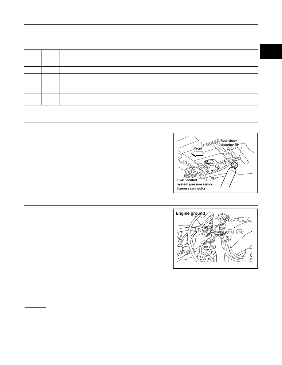
Check rubber tube connected to the sensor for clogging, vent,
kink, disconnection or improper connection.

OK or NG

OK

>> GO TO 2.

NG

>> Reconnect, repair or replace.

2. 

RETIGHTEN GROUND SCREWS

1.

Loosen and retighten engine ground screws.

>> GO TO 3.

3. 

 CHECK CONNECTOR

1.

Disconnect EVAP control system pressure sensor harness connector.

2.

Check sensor harness connector for water.
Water should not exist.

OK or NG

OK

>> GO TO 4.

NG

>> Repair or replace harness connector.

TER-

MINAL 

NO.

WIRE 

COLOR

ITEM

CONDITION 

DATA (DC Voltage)

42

B/W

Sensor power supply

[Ignition switch: ON]

Approximately 5V

43

BR

Sensor ground

[Engine is running]

Warm-up condition

Idle speed

Approximately 0V

62

Y

EVAP control system pres-
sure sensor

[Ignition switch: ON]

Approximately 1.8 - 4.8V

AEC651A

BBIA0418E

EC-944

[VG33E]

DTC P0453 EVAP CONTROL SYSTEM PRESSURE SENSOR

4. 

CHECK EVAP CONTROL SYSTEM PRESSURE SENSOR POWER SUPPLY CIRCUIT

1.

 Turn ignition switch ON.

2.

Check voltage between terminal 3 and ground with CONSULT-II
or tester.

OK or NG

OK

>> GO TO 6.

NG

>> GO TO 5.

5. 

DETECT MALFUNCTIONING PART

Check the following.

Harness connectors C3, B113 and B101, M67

Harness connectors M58, F28

Harness for open or short between EVAP control system pressure sensor and ECM

>> Repair harness or connectors.

6. 

CHECK EVAP CONTROL SYSTEM PRESSURE SENSOR GROUND CIRCUIT FOR OPEN AND 

SHORT

1.

Turn ignition switch OFF.

2.

Check harness continuity between EVAP control system pressure sensor terminal 1 and engine ground.
Refer to Wiring Diagram.

3.

Also check harness for short to power.

OK or NG

OK >> GO 

TO 

8.

NG

>> GO TO 7.

7. 

DETECT MALFUNCTIONING PART

Check the following.

Harness connectors C3, B113 and B101, M67

Harness connectors M59, F27

Joint connector-4

Harness for open or short between EVAP control system pressure sensor and ECM

>> Repair open circuit or short to power in harness or connectors.

Voltage: Approximately 5V

SEF889U

Continuity should exist.

DTC P0453 EVAP CONTROL SYSTEM PRESSURE SENSOR

EC-945

[VG33E]

C

D

E

F

G

H

I

J

K

L

M

A

EC

8. 

CHECK EVAP CONTROL SYSTEM PRESSURE SENSOR INPUT SIGNAL CIRCUIT FOR OPEN AND 

SHORT

1.

Disconnect ECM harness connector.

2.

Check harness continuity between ECM terminal 62 and EVAP control system pressure sensor terminal
2.
Refer to Wiring Diagram.

3.

Also check harness for short to ground and short to power.

OK or NG

OK

>> GO TO 10.

NG

>> GO TO 9.

9. 

DETECT MALFUNCTIONING PART

Check the following.

Harness connectors C3, B113 and B101, M67

Harness connectors M59, F27

Harness for open or short between ECM and EVAP control system pressure sensor

>> Repair open circuit or short to ground or short to power in harness or connectors.

Continuity should exist.

EC-946

[VG33E]

DTC P0453 EVAP CONTROL SYSTEM PRESSURE SENSOR

10. 

CHECK EVAP CANISTER VENT CONTROL VALVE

 With CONSULT-II

1.

Perform “VENT CONTROL/V” in “ACTIVE TEST” mode.

2.

Check air passage continuity and operation delay time under the
following conditions.

Operation takes less than 1 second.

 Without CONSULT-II

1.

Check air passage continuity and operation delay time under the
following conditions.

Operation takes less than 1 second.
If NG or operation takes more than 1 second, clean valve using
air blower or replace as necessary.
If portion B  is rusted, replace control valve.
Make sure new O-ring is installed properly.

OK or NG

OK

>> GO TO 11.

NG

>> Replace EVAP canister vent control valve.

11. 

CHECK EVAP CONTROL SYSTEM PRESSURE SENSOR

1.

Remove EVAP control system pressure sensor with its harness connector connected.

2.

Remove hose from EVAP control system pressure sensor.

3.

Turn ignition switch ON.

4.

Use pump to apply vacuum and pressure to EVAP control system pressure sensor as shown in figure.

5.

Check input voltage between ECM terminal 62 and ground.

CAUTION:

Always calibrate the vacuum pump gauge when using it.

Do not apply below 

93.3 kPa (700 mmHg, 27.56 inHg) or

over 101.3 kPa (760 mmHg, 29.92 inHg) of pressure.

OK or NG

OK

>> GO TO 12.

NG

>> Replace EVAP control system pressure sensor.

Condition

VENT CONTROL/V

Air passage continuity 

between A and B

ON

No

OFF

Yes

SEF013Z

Condition

Air passage continuity 

between A and B

12V direct current supply between 
terminals 1 and 2

No

OFF

Yes

BBIA0309E

Applied vacuum

Voltage V

Not applied

1.8 - 4.8

−26.7 kpa (−200 mmHg, −7.87 inHg)

2.1 to 2.5 V lower than above value

PBIB1426E


Content   ..  458  459  460  461   ..