Nissan Frontier D22. Manual - part 449


  Index      Nissan     Nissan Frontier D22 Pickup (1998-2004 year) - Service and Repair Manual


Search            


Content   ..  447  448  449  450   ..


Nissan Frontier D22. Manual - part 449


DTC P0420, P0430 THREE WAY CATALYST FUNCTION

EC-899

[VG33E]

C

D

E

F

G

H

I

J

K

L

M

A

EC

5. 

CHECK INJECTORS

1.

Refer to Wiring Diagram for Injectors, 

EC-1141

 .

2.

Stop engine and then turn ignition switch ON.
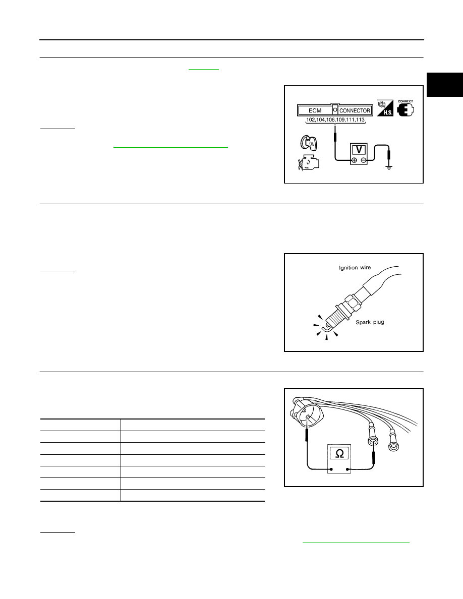
3.

Check voltage between ECM terminals 102, 104, 106, 109, 111
and 113 and ground with CONSULT-II or tester.

OK or NG

OK

>> GO TO 6.

NG

>> Perfor

EC-1140, "INJECTOR CIRCUIT"

 .

6. 

CHECK IGNITION SPARK

1.

Turn ignition switch OFF.

2.

Disconnect ignition wire from spark plug.

3.

Connect a known good spark plug to the ignition wire.

4.

Place end of spark plug against a suitable ground and crank engine.

5.

Check for spark.

OK or NG

OK

>> GO TO 8.

NG

>> GO TO 7.

7. 

CHECK IGNITION WIRES

1.

Inspect wires for cracks, damage, burned terminals and for improper fit.

2.

Measure the resistance of wires to their distributor cap terminal.
Move each wire while testing to check for intermittent breaks.
Resistance:

If the resistance exceeds the above specification, inspect ignition wire to distributor cap connection. Clean
connection or replace the ignition wire with a new one.

OK or NG

OK

>> Check ignition coil, power transistor and their circuits. Refer to 

EC-1134, "IGNITION SIGNAL"

 .

NG

>> Replace.

Battery voltage should exist.

SEF711U

SEF282G

Cylinder No.

Resistance k

Ω [at 25°C (77°F)]

1

Approx. 6.5

2

Approx. 10.0

3

Approx. 8.5

4

Approx. 12.5

5

Approx. 8.5

6

Approx. 11.0

SEF174P

EC-900

[VG33E]

DTC P0420, P0430 THREE WAY CATALYST FUNCTION

8. 

CHECK INJECTOR

1.

Turn ignition switch OFF.

2.

Remove injector assembly.
Refer to 

EM-80, "OUTER COMPONENT PARTS"

 .

Keep fuel hose and all injectors connected to injector gallery.

3.

Disconnect all ignition coil harness connectors.

4.

Turn ignition switch ON.
Make sure fuel does not drip from injector.

OK or NG

OK (Does not drip)>>GO TO 9.
NG (Drips)>>Replace the injector(s) from which fuel is dripping.

9. 

CHECK INTERMITTENT INCIDENT

Refer to 

EC-696, "TROUBLE DIAGNOSIS FOR INTERMITTENT INCIDENT"

 .

Trouble is fixed>>INSPECTION END.
Trouble is not fixed>>Replace three way catalyst (manifold).

DTC P0441 EVAP CONTROL SYSTEM

EC-901

[VG33E]

C

D

E

F

G

H

I

J

K

L

M

A

EC

DTC P0441 EVAP CONTROL SYSTEM

PFP:14950

System Description

UBS00DKO

NOTE:
If DTC P0441 is displayed with P0510, perform trouble diagnosis for DTC P0510 first. (See 

EC-992

 .)

In this evaporative emission (EVAP) control system, purge flow occurs during non-closed throttle conditions.
Purge volume is related to air intake volume. Under normal purge conditions (non-closed throttle), the EVAP
canister purge volume control solenoid valve is open. Purge flow exposes the EVAP control system pressure
sensor to intake manifold vacuum.

On Board Diagnosis Logic

UBS00DKP

Under normal conditions (non-closed throttle), sensor output voltage indicates if pressure drop and purge flow
are adequate. If not, a malfunction is determined.

DTC Confirmation Procedure

UBS00DKQ

CAUTION:

Always drive vehicle at a safe speed.

NOTE:
If DTC Confirmation Procedure has been previously conducted, always turn ignition switch OFF and wait at
least 5 seconds before conducting the next test.
TESTING CONDITION:
Always perform test at a temperature of 5

°C (41°F) or more.

PBIB1438E

DTC No.

Trouble diagnosis name

DTC detecting condition

Possible cause

P0441

EVAP control system 
incorrect purge flow

EVAP control system does not operate prop-
erly, EVAP control system has a leak between 
intake manifold and EVAP control system pres-
sure sensor.

EVAP canister purge volume control 
solenoid valve stuck closed

EVAP control system pressure sensor 
and the circuit

Loose, disconnected or improper con-
nection of rubber tube

Blocked rubber tube

Cracked EVAP canister

EVAP canister purge volume control 
solenoid valve circuit

Closed throttle position switch

Blocked purge port

EVAP canister vent control valve

EC-902

[VG33E]

DTC P0441 EVAP CONTROL SYSTEM

 WITH CONSULT-II

1.

Start engine and warm it up to normal operating temperature.

2.

Turn ignition switch OFF and wait at least 5 seconds.

3.

Start engine and let it idle for at least 70 seconds.

4.

Select “PURG FLOW P0441” of “EVAPORATIVE SYSTEM” in “DTC WORK SUPPORT” mode with CON-
SULT-II.

5.

Touch “START”.
If “COMPLETED” is displayed, go to step 7.

6.

When the following conditions are met, “TESTING” will be displayed on the CONSULT-II screen. Maintain
the conditions continuously until “TESTING” changes to “COMPLETED”. (It will take at least 35 seconds.)

If “TESTING” is not changed for a long time, retry from step 2.

7.

Make sure that “OK” is displayed after touching “SELF-DIAG RESULTS”. If “NG” is displayed, refer to 

EC-

903, "Diagnostic Procedure"

 .

Overall Function Check

UBS00DKR

Use this procedure to check the overall monitoring function of the EVAP control system purge flow monitoring.
During this check, a DTC might not be confirmed.

 WITH GST

1.

Lift up drive wheels.

2.

Start engine and warm it up to normal operating temperature.

3.

Turn ignition switch OFF and wait at least 5 seconds.

4.

Start engine and wait at least 70 seconds.

5.

Set voltmeter probes to ECM terminals 62 (EVAP control system
pressure sensor signal) and ground.

6.

Check EVAP control system pressure sensor value at idle speed
and note it.

7.

Establish and maintain the following conditions for at least 1
minute.

8.

Verify that EVAP control system pressure sensor value stays 0.1V less than the value at idle speed (mea-
sured at step 6) for at least 1 second.

Selector lever

Suitable position

VHCL SPEED SE

32 - 120 km/h (20 - 75 MPH)

ENG SPEED

500 - 3,400 rpm

B/FUEL SCHDL

1.0 - 10.0 msec

COOLAN TEMP/S

0 - 119

°C (32 - 246°F)

PBIB0826E

Air conditioner switch

ON

Headlamp switch

ON

Rear window defogger switch

ON

Engine speed

Approx. 3,000 rpm

Gear position

Any position other than P, N or R

SEF906U


Content   ..  447  448  449  450   ..