Nissan Frontier D22. Manual - part 429


  Index      Nissan     Nissan Frontier D22 Pickup (1998-2004 year) - Service and Repair Manual


Search            


Content   ..  427  428  429  430   ..


Nissan Frontier D22. Manual - part 429


DTC P0139, P0159 HO2S2

EC-819

[VG33E]

C

D

E

F

G

H

I

J

K

L

M

A

EC

7. 

CHECK HEATED OXYGEN SENSOR 2

 Without CONSULT-II

1.

Turn ignition switch OFF and wait at least 10 seconds. 

2.

Stop vehicle with engine running.

3.

Start engine and keep the engine speed between 3,500 and 4,000 rpm for at least 1 minute under no load.

4.

Let engine idle for 1 minute.
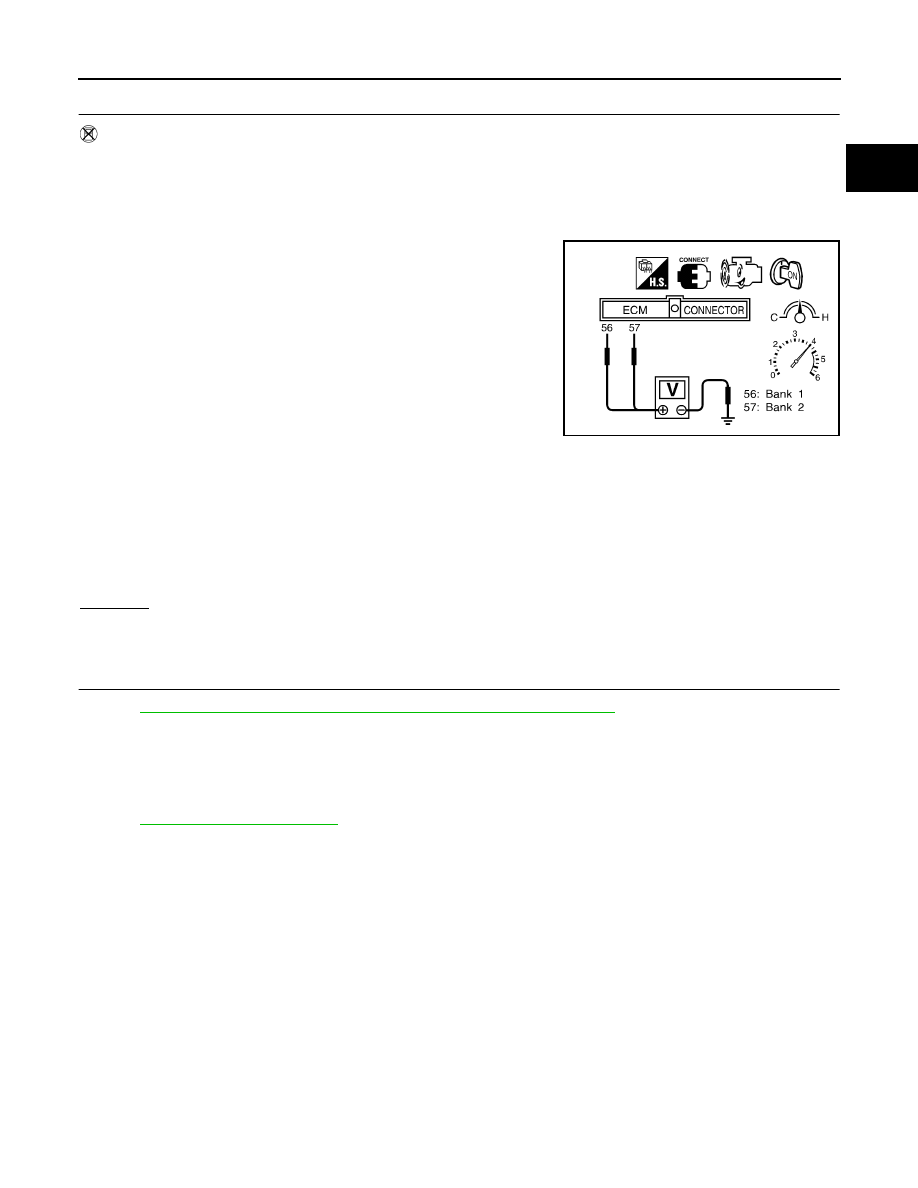
5.

Set voltmeter probes between ECM terminal 56 [HO2S2 (B1)
signal] or 57 [HO2S2 (B2) signal] and engine ground.

6.

Check the voltage when revving up to 4,000 rpm under no load
at least 10 times.
(Depress and release accelerator pedal as soon as possible.)
The voltage should be above 0.62V at least once during this
procedure.
If the voltage is above 0.62V at step 6, step 7 is not neces-
sary.

7.

Keep vehicle at idling for 10 minutes, then check voltage. Or
check the voltage when coasting from 80 km/h (50 MPH) in D
position with “OD” OFF (A/T), 3rd gear position (M/T).
The voltage should be below 0.48V at least once during this procedure.

8.

If NG, replace heated oxygen sensor 2.

CAUTION:

Discard any heated oxygen sensor which has been dropped from a height of more than 0.5 m (19.7
in) onto a hard surface such as a concrete floor; use a new one.

Before installing new oxygen sensor, clean exhaust system threads using Oxygen Sensor Thread
Cleaner tool J-43897-18 or J-43897-12 and approved anti-seize lubricant.

OK or NG

OK

>> GO TO 8.

NG

>> Replace malfunctioning heated oxygen sensor 2.

8. 

CHECK INTERMITTENT INCIDENT

Refer to 

EC-696, "TROUBLE DIAGNOSIS FOR INTERMITTENT INCIDENT"

 .

>> INSPECTION END.

Removal and Installation

UBS00DIP

HEATED OXYGEN SENSOR 2

Refer to 

EX-3, "EXHAUST SYSTEM"

 .

SEF922UA

EC-820

[VG33E]

DTC P0171, P0174 FUEL INJECTION SYSTEM FUNCTION

DTC P0171, P0174 FUEL INJECTION SYSTEM FUNCTION

PFP:16600

On Board Diagnosis Logic

UBS00DIQ

With the Air-Fuel Mixture Ratio Self-Learning Control, the actual mixture ratio can be brought closely to the
theoretical mixture ratio based on the mixture ratio feedback signal from the heated oxygen sensors 1. The
ECM calculates the necessary compensation to correct the offset between the actual and the theoretical
ratios.
In case the amount of the compensation value is extremely large (The actual mixture ratio is too lean.), the
ECM judges the condition as the fuel injection system malfunction and lights up the MIL (2 trip detection logic).

DTC Confirmation Procedure

UBS00DIR

NOTE:
If DTC Confirmation Procedure has been previously conducted, always turn ignition switch OFF and wait at
least 5 seconds before conducting the next test.

 WITH CONSULT-II

1.

Start engine and warm it up to normal operating temperature.

2.

Turn ignition switch OFF and wait at least 5 seconds.

3.

Turn ignition switch ON and select “SELF-LEARNING CONT” in “WORK SUPPORT” mode with CON-
SULT-II.

4.

Clear the self-learning control coefficient by touching “CLEAR”.

5.

Select “DATA MONITOR” mode with CONSULT-II.

6.

Start engine again and let it idle for at least 10 minutes.
The 1st trip DTC P0171 or P0174 should be detected at this
stage, if a malfunction exists. If so, go to 

EC-824, "Diagnostic

Procedure"

 .

7.

If it is difficult to start engine at step 6, the fuel injection system
has a malfunction, too.

8.

Crank engine while depressing accelerator pedal. If engine
starts, go to 

EC-824, "Diagnostic Procedure"

 . If engine does not

start, check exhaust and intake air leak visually.

 WITH GST

1.

Start engine and warm it up to normal operating temperature.

2.

Turn ignition switch OFF and wait at least 5 seconds.

3.

Disconnect mass air flow sensor harness connector. Then restart and run engine for at least 5 seconds at
idle speed.

4.

Stop engine and reconnect mass air flow sensor harness connector.

5.

Select MODE 3 with GST. Make sure DTC P0102 is detected.

6.

Select MODE 4 with GST and erase the DTC P0102.

7.

Start engine again and let it idle for at least 10 minutes.

Sensor

Input signal to ECM

ECM function

Actuator

Heated oxygen sensors 1

Density of oxygen in exhaust gas
(Mixture ratio feedback signal)

Fuel injection 
control

Fuel injector

DTC No.

Trouble diagnosis 

name

DTC detecting condition

Possible cause

P0171
(Bank 1)

Fuel injection system 
too lean

Fuel injection system does not operate properly.

The amount of mixture ratio compensation is too 
large. (The mixture ratio is too lean.)

Intake air leaks

Heated oxygen sensor 1

Fuel injector

Exhaust gas leaks

Incorrect fuel pressure

Lack of fuel

Mass air flow sensor

Incorrect PCV hose connection

P0174
(Bank 2)

SEF968Y

DTC P0171, P0174 FUEL INJECTION SYSTEM FUNCTION

EC-821

[VG33E]

C

D

E

F

G

H

I

J

K

L

M

A

EC

8.

Select MODE 7 with GST. The 1st trip DTC P0171 or P0174 should be detected at this stage, if a malfunc-
tion exists. If so, go to 

EC-824, "Diagnostic Procedure"

 .

9.

If it is difficult to start engine at step 7, the fuel injection system has a malfunction.

10. Crank engine while depressing accelerator pedal. If engine starts, go to 

EC-824, "Diagnostic Procedure"

 .

If engine does not start, check exhaust and intake air leak visually.

EC-822

[VG33E]

DTC P0171, P0174 FUEL INJECTION SYSTEM FUNCTION

Wiring Diagram

UBS00DIS

BANK 1

BBWA1082E


Content   ..  427  428  429  430   ..