Nissan Frontier D22. Manual - part 399
POWER SUPPLY CIRCUIT FOR ECM
EC-699
[VG33E]
C
D
E
F
G
H
I
J
K
L
M
A
EC
2.
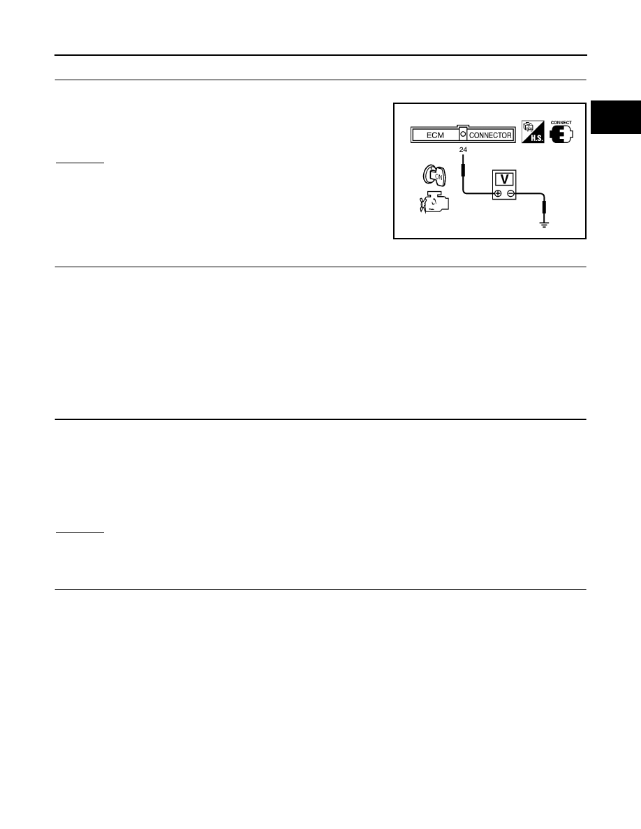
CHECK ECM POWER SUPPLY CIRCUIT-I
1.
Turn ignition switch OFF and then ON.
2.
Check voltage between ECM terminal 24 and ground with CON-
SULT-II or tester.
OK or NG
OK
>> GO TO 4.
NG
>> GO TO 3.
3.
DETECT MALFUNCTIONING PART
Check the following.
●
Harness connectors E43, M65
●
Harness connectors M5, F27
●
Fuse block (J/B) connector E49
●
10A fuse
●
Harness for open or short between ECM and fuse
>> Repair harness or connectors.
4.
CHECK ECM GROUND CIRCUIT-I FOR OPEN AND SHORT
1.
Turn ignition switch OFF.
2.
Disconnect ECM harness connector.
3.
Check harness continuity between ECM terminals 10, 19, 25, 32, 116, 124 and engine ground.
Refer to WIRING DIAGRAM.
4.
Also check harness for short to power.
OK or NG
OK
>> GO TO 15.
NG
>> GO TO 5.
5.
DETECT MALFUNCTIONING PART
Check the following.
●
Harness for open between ECM and engine ground
>> Repair open circuit or short to power in harness or connectors.
Voltage: Battery voltage
SEF674U
Continuity should exist.