Nissan Frontier D22. Manual - part 360
INJECTOR CIRCUIT
EC-543
[KA24DE]
C
D
E
F
G
H
I
J
K
L
M
A
EC
3.
DETECT MALFUNCTIONING PART
Check the following.
●
Harness connectors F27, M59
●
Fuse block (J/B) connector M26
●
10A fuse
●
Harness for open or short between injector and fuse
>> Repair harness or connectors.
4.
CHECK OUTPUT SIGNAL CIRCUIT
1.
Turn ignition switch OFF.
2.
Disconnect ECM harness connector.
3.
Check harness continuity between injector terminal 2 and ECM terminals 102, 104, 109, 111.
Refer to Wiring Diagram.
4.
Also check harness for short to ground and short to power.
OK or NG
OK
>> GO TO 6.
NG
>> GO TO 5.
5.
DETECT MALFUNCTIONING PART
Check the harness for open or short between ECM and injector.
>> Repair open circuit or short to ground or short to power in harness or connectors.
6.
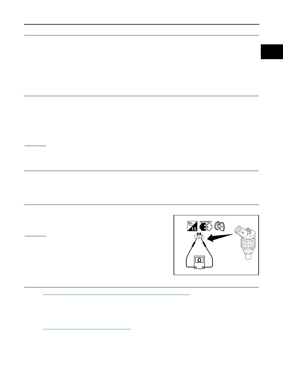
CHECK INJECTOR
1.
Disconnect injector harness connector.
2.
Check resistance between terminals as shown in the figure.
OK or NG
OK
>> GO TO 7.
NG
>> Replace injector.
7.
CHECK INTERMITTENT INCIDENT
Perform
EC-120, "TROUBLE DIAGNOSIS FOR INTERMITTENT INCIDENT"
>> INSPECTION END
Removal and Installation
UBS00DD8
INJECTOR
Refer to
EM-13, "OUTER COMPONENT PARTS"
.
Continuity should exist.
Resistance
: 7.3 - 9.9
Ω [at 25°C (77°F)]
SEF273W