Nissan Frontier D22. Manual - part 330


  Index      Nissan     Nissan Frontier D22 Pickup (1998-2004 year) - Service and Repair Manual


Search            


Content   ..  328  329  330  331   ..


Nissan Frontier D22. Manual - part 330


DTC P1144 HO2S1

EC-423

[KA24DE]

C

D

E

F

G

H

I

J

K

L

M

A

EC

2.

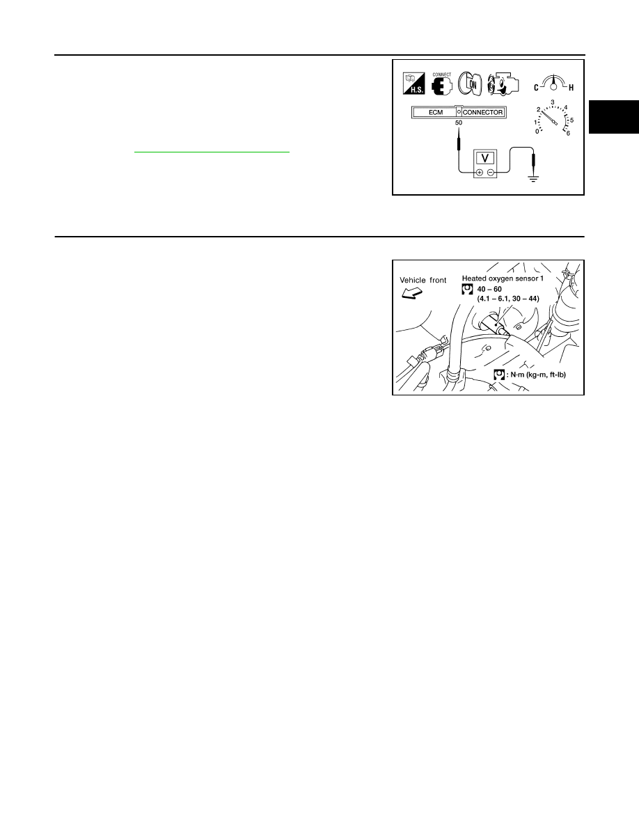
Set voltmeter probes between ECM terminal 50 (Heated oxygen
sensor 1 signal) and ECM ground.

3.

Check the following with engine speed held at 2,000 rpm con-
stant under no load.

The maximum voltage is below 0.8V at least 1 time.

The minimum voltage is below 0.35V at least 1 time.

4.

If NG, go to 

EC-423, "Diagnostic Procedure"

 .

Diagnostic Procedure

UBS00DA0

1. 

RETIGHTEN HEATED OXYGEN SENSOR 1

1.

Turn ignition switch OFF.

2.

Loosen and retighten heated oxygen sensor 1.

>> GO TO 2.

AEC873A

Tightening torque

: 40 - 60 N·m
(4.1 - 6.1 kg-m, 30 - 44 ft-lb)

BBIA0429E

EC-424

[KA24DE]

DTC P1144 HO2S1

2. 

CLEAR THE SELF-LEARNING DATA

 With CONSULT-II

1.

Start engine and warm it up to normal operating temperature.

2.

Select “SELF-LEARNING CONT” in “ACTIVE TEST” mode with CONSULT-II.

3.

Clear the self-learning control coefficient by touching “CLEAR”.

4.

Run engine for at least 10 minutes at idle speed.
Is the 1st trip DTC P0172 detected?
Is it difficult to start engine?

 Without CONSULT-II

1.

Start engine and warm it up to normal operating temperature.

2.

Turn ignition switch OFF.

3.

Disconnect mass air flow sensor harness connector, and restart
and run engine for at least 3 seconds at idle speed.

4.

Stop engine and reconnect mass air flow sensor harness con-
nector.

5.

Make sure DTC P0102 is displayed.

6.

Erase the DTC memory. Refer to 

EC-61, "HOW TO ERASE

EMISSION-RELATED DIAGNOSTIC INFORMATION"

 .

7.

Make sure DTC P0000 is displayed.

8.

Run engine for at least 10 minutes at idle speed.
Is the 1st trip DTC P0171 detected?
Is it difficult to start engine?

Yes or No

Yes

>> Perform trouble diagnosis for DTC P0172. Refer to 

EC-232

 .

No

>> GO TO 3.

3. 

CHECK HARNESS CONNECTOR

1.

Turn ignition switch OFF.

2.

Disconnect heated oxygen sensor 1 harness connector.

3.

Check harness connector for water. 
Water should not exit.

OK or NG

OK

>> GO TO 4.

NG

>> Repair or replace harness connector.

SEF215Z

AEC131A

DTC P1144 HO2S1

EC-425

[KA24DE]

C

D

E

F

G

H

I

J

K

L

M

A

EC

4. 

CHECK HEATED OXYGEN SENSOR 1 HEATER

Check resistance between terminals 3 and 1.

Check continuity between terminals 2 and 1, 3 and 2.

CAUTION:

Discard any heated oxygen sensor which has been dropped
from a height of more than 0.5 m (19.7 in) onto a hard sur-
face such as a concrete floor; use a new one.

Before installing new oxygen sensor, clean exhaust system
threads using Oxygen Sensor Thread Cleaner tool J-43897-
18 or J-43897-12 and approved anti-seize lubricant.

OK or NG

OK

>> GO TO 5.

NG

>> Replace heated oxygen sensor 1.

5. 

CHECK HEATED OXYGEN SENSOR 1

Refer to 

EC-207, "Component Inspection"

 .

OK or NG

OK

>> GO TO 7.

NG

>> Replace heated oxygen sensor 1.

6. 

CHECK INTERMITTENT INCIDENT

Perform 

EC-120, "TROUBLE DIAGNOSIS FOR INTERMITTENT INCIDENT"

 .

Refer to 

EC-205, "Wiring Diagram"

 , for circuit.

>> INSPECTION END.

Removal and Installation

UBS00DA1

HEATED OXYGEN SENSOR 1

Refer to 

EM-13, "OUTER COMPONENT PARTS"

 .

Resistance

: 3.3 - 4.0 

 [at 25°C (77°F)]

Continuity should not exist.

SEF220W

EC-426

[KA24DE]

DTC P1146 HO2S2

DTC P1146 HO2S2

PFP:226A0

Component Description

UBS00DA2

The heated oxygen sensor 2, after three way catalyst (manifold),
monitors the oxygen level in the exhaust gas.
Even if switching characteristics of the heated oxygen sensor 1 are
shifted, the air-fuel ratio is controlled to stoichiometric, by the signal
from the heated oxygen sensor 2.
This sensor is made of ceramic zirconia. The zirconia generates volt-
age from approximately 1V in richer conditions to 0V in leaner condi-
tions.
Under normal conditions the heated oxygen sensor 2 is not used for
engine control operation.

CONSULT-II Reference Value in Data Monitor Mode

UBS00DA3

Specification data are reference values.

On Board Diagnosis Logic

UBS00DA4

The heated oxygen sensor 2 has a much longer switching time
between rich and lean than the heated oxygen sensor 1. The oxygen
storage capacity before the three way catalyst (manifold) causes the
longer switching time. To judge the malfunctions of heated oxygen
sensor 2, ECM monitors whether the minimum voltage of the sensor
is sufficiently low during various driving conditions such as fuel-cut.

SEF327R

MONITOR ITEM

CONDITION

SPECIFICATION

HO2S2 (B1)

Engine: After warming up

Keeping the engine speed 
between 3,500 and 4,000 rpm 
for 1 minute and at idle for 1 
minute under no load

Revving engine from idle up to 3,000 
rpm quickly.

0 - 0.3V 

←→ Approx. 0.6 - 1.0V

HO2S2 MNTR (B1)

Engine: After warming up

Keeping the engine speed 
between 3,500 and 4,000 rpm 
for 1 minute and at idle for 1 
minute under no load

Revving engine from idle up to 3,000 
rpm quickly.

LEAN 

←→ RICH

MBIB1080E

DTC No.

Trouble diagnosis name

DTC detecting condition

Possible Cause

P1146

Heated oxygen sensor 2 
minimum voltage monitoring

The minimum voltage from the sensor is not 
reached to the specified voltage.

Harness or connectors
(The sensor circuit is open or shorted.)

Heated oxygen sensor 2 

Fuel pressure

Fuel injector


Content   ..  328  329  330  331   ..