Nissan Frontier D22. Manual - part 297
DTC P0402 EGRC-BPT VALVE FUNCTION
EC-291
[KA24DE]
C
D
E
F
G
H
I
J
K
L
M
A
EC
8.
CHECK EGR VALVE
Refer to
EC-291, "Component Inspection"
OK or NG
OK
>> GO TO 9.
NG
>> Replace EGR valve.
9.
CHECK INTERMITTENT INCIDENT
Perform
EC-120, "TROUBLE DIAGNOSIS FOR INTERMITTENT INCIDENT"
>> INSPECTION END.
Component Inspection
UBS00D6V
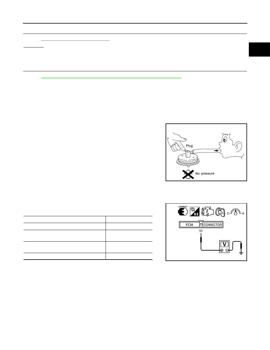
EGRC-BPT VALVE
1.
Plug one of two ports of EGRC-BPT valve.
2.
Vacuum from the other port and check leakage without applying any pressure from under EGR-BPT
valve.
Leakage should exist.
MASS AIR FLOW SENSOR
1.
Turn ignition switch ON.
2.
Start engine and warm it up to normal operating temperature.
3.
Check voltage between ECM terminal 54 (mass air flow sensor
signal) and ground.
*: Check for linear voltage rise in response to increases to about 4,000 rpm in
engine speed.
4.
If the voltage is out of specification, disconnect mass air flow sensor harness connector and connect it
again. Repeat above check.
SEF172P
Conditions
Voltage [V]
Ignition switch ON (Engine stopped.)
Less than 1.0
Idle (Engine is warmed-up to normal operating
temperature.)
0.9 - 1.8
2,500 rpm (Engine is warmed-up to normal
operating temperature.)
1.9 - 2.3
Idle to about 4,000 rpm*
1.3 - 1.7 to Approx. 3.0
SEF326V