Index Nissan Nissan Frontier D22 Pickup (1998-2004 year) - Service and Repair Manual
Search
Content .. 275 276 277 278 ..
Nissan Frontier D22. Manual - part 277
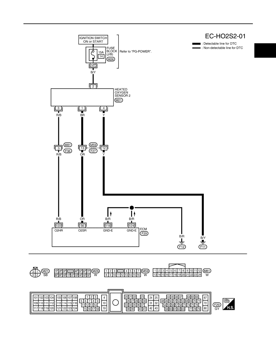
DTC P0138 HO2S2
EC-211
[KA24DE]
C
D
E
F
G
H
I
J
K
L
M
A
EC
Wiring Diagram
UBS00D4N
BBWA1057E