Nissan Frontier D22. Manual - part 271


  Index      Nissan     Nissan Frontier D22 Pickup (1998-2004 year) - Service and Repair Manual


Search            


Content   ..  269  270  271  272   ..


Nissan Frontier D22. Manual - part 271


DTC P0132 HO2S1

EC-187

[KA24DE]

C

D

E

F

G

H

I

J

K

L

M

A

EC

DTC Confirmation Procedure 

UBS00D3W

NOTE:
If “DTC Confirmation Procedure” has been previously conducted, always turn ignition switch OFF and wait at
least 5 seconds before conducting the next test.

 WITH CONSULT-II

1.

 Start engine and warm it up to normal operating temperature.

2.

Turn ignition switch OFF and wait at least 5 seconds.

3.

Turn ignition switch ON.

4.

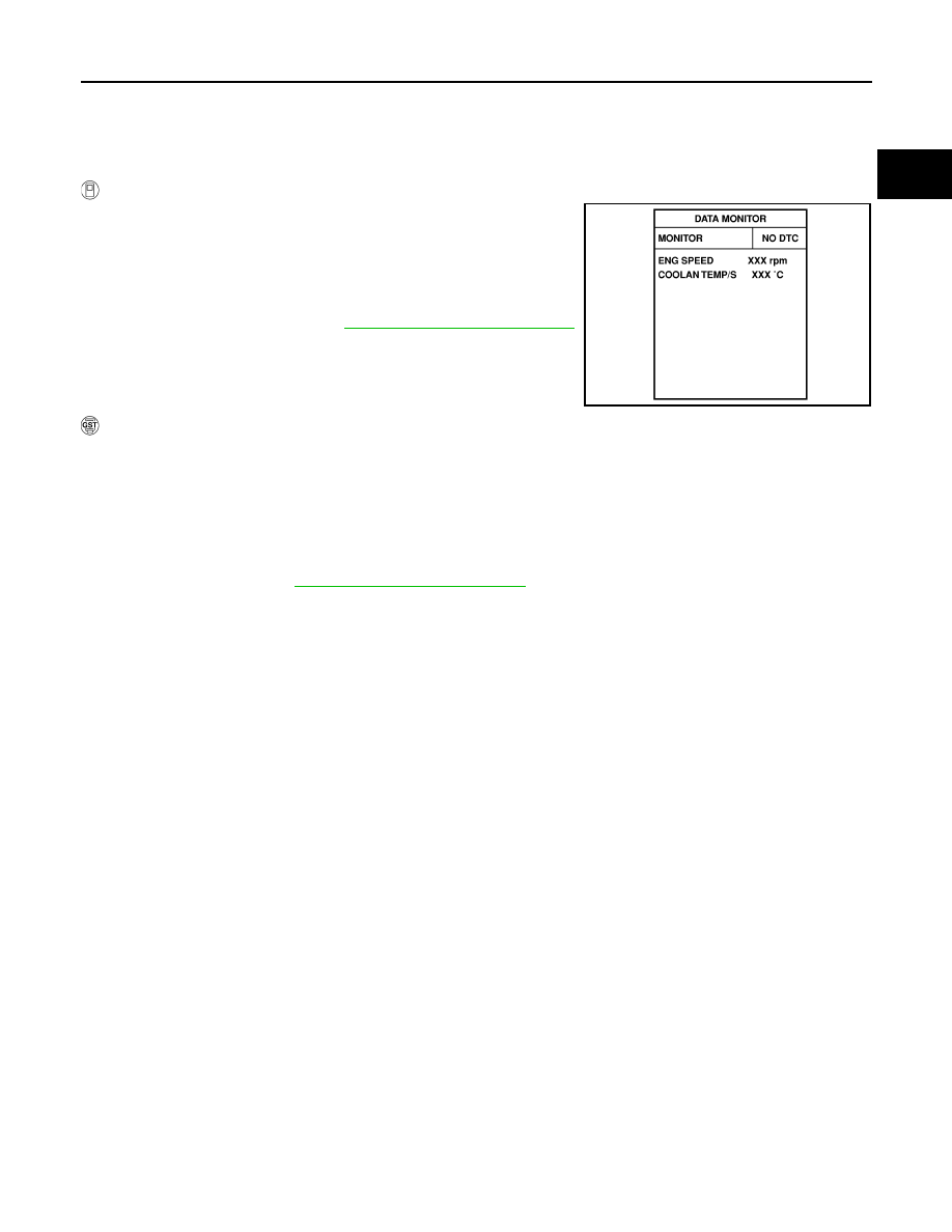
Select “DATA MONITOR” mode with CONSULT-II.

5.

Restart engine and let it idle for 2 minutes.

6.

If 1st trip DTC is detected, go to 

EC-189, "Diagnostic Procedure"

.

 WITH GST

1.

Start engine and warm it up to normal operating temperature.

2.

Turn ignition switch OFF and wait at least 5 seconds.

3.

Restart engine and let it idle for 2 minutes.

4.

Turn ignition switch OFF and wait at least 5 seconds.

5.

Restart engine and let it idle for 2 minutes.

6.

Select “MODE 3” with GST.

7.

If DTC is detected, go to 

EC-189, "Diagnostic Procedure"

 .

When using GST, “DTC Confirmation Procedure” should be performed twice as much as when
using CONSULT-II because GST cannot display MODE 7 (1st trip DTC) concerning this diagnosis.
Therefore, using CONSULT-II is recommended.

SEF174Y

EC-188

[KA24DE]

DTC P0132 HO2S1

Wiring Diagram

UBS00D3X

BBWA0440E

DTC P0132 HO2S1

EC-189

[KA24DE]

C

D

E

F

G

H

I

J

K

L

M

A

EC

Specification data are reference values and are measured between each terminal and ground.

CAUTION:

Do not use ECM ground terminals when measuring input/output voltage. Doing so may result in dam-
age to the ECM's transistor. Use a ground other than ECM terminals, such as the ground.

Diagnostic Procedure

UBS00D3Y

1. 

RETIGHTEN HEATED OXYGEN SENSOR 1

1.

Turn ignition switch OFF.

2.

Loosen and retighten heated oxygen sensor 1.

>> GO TO 2.

2. 

CHECK INPUT SIGNAL CIRCUIT

1.

Disconnect heated oxygen sensor 1 harness connector and
ECM harness connector.

2.

Check harness continuity between ECM terminal 50 and HO2S1 terminal 2.
Refer to Wiring Diagram.

3.

Check harness continuity between ECM terminal 50 or HO2S1 terminal 2 and ground.
Refer to Wiring Diagram.

4.

Also check harness for short to power.

OK or NG

OK

>> GO TO 3.

NG

>> Repair open circuit or short to ground or short to power in harness or connectors.

TER-

MINAL 

NO.

WIRE 

COLOR

ITEM

CONDITION

DATA (DC Voltage)

50

B

Heated oxygen sensor 
1

[Engine is running]

Warm-up condition

Engine speed is 2,000 rpm

0 - Approximately 1.0V
(Periodically change)

Tightening torque  : 40 - 60 N·m

(4.1 - 6.1 kg-m, 30 - 44 ft-lb)

BBIA0429E

BBIA0430E

Continuity should exist.

Continuity should not exist.

EC-190

[KA24DE]

DTC P0132 HO2S1

3. 

CHECK HARNESS CONNECTOR

Check heated oxygen sensor 1 harness connector for water.
Water should not exist.

OK or NG

OK

>> GO TO 4.

NG

>> Repair or replace harness connector.

4. 

CHECK HEATED OXYGEN SENSOR 1

Refer to 

EC-190, "Component Inspection"

 .

OK or NG

OK

>> GO TO 5.

NG

>> Replace heated oxygen sensor 1.

5. 

CHECK INTERMITTENT INCIDENT

Perform 

EC-120, "TROUBLE DIAGNOSIS FOR INTERMITTENT INCIDENT"

 .

>> INSPECTION END.

Component Inspection

UBS00D3Z

HEATED OXYGEN SENSOR 1

 With CONSULT-II

1.

Reconnect all harness connectors disconnected.

2.

Start engine and warm it up to normal operating temperature.

3.

Select “MANU TRIG” in “DATA MONITOR” mode, and the trigger point is adjusted to 100%.

4.

Select “HO2S1 (B1)” and “HO2S1 MNTR (B1)” in item selection.

5.

Hold engine speed at 2,000 rpm under no load during the follow-
ing steps.

6.

Touch “START” on CONSULT-II screen.

7.

Check the following.

“HO2S1 MNTR (B1)” in “DATA MONITOR” mode changes from
“RICH” to “LEAN” to “RICH” 5 times in 10 seconds.
5 times (cycles) are counted as shown below:

“HO2S1 (B1)” voltage goes above 0.6V at least once.

“HO2S1 (B1)” voltage goes below 0.3V at least once.

“HO2S1 (B1)” voltage never exceeds 1.0V.

SEF646Y

SEF217YA


Content   ..  269  270  271  272   ..