Nissan Frontier D22. Manual - part 262
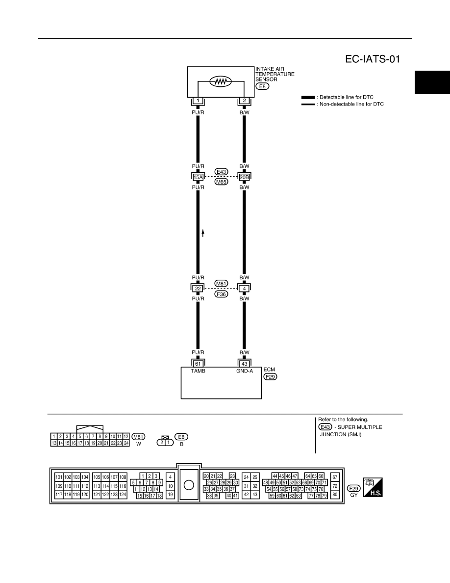
DTC P0112, P0113 IAT SENSOR
EC-151
[KA24DE]
C
D
E
F
G
H
I
J
K
L
M
A
EC
Wiring Diagram
UBS00D2R
BBWA1056E
|
|
|
DTC P0112, P0113 IAT SENSOR EC-151 [KA24DE] C D E F G H I J K L M A EC Wiring Diagram UBS00D2R BBWA1056E |