Nissan Frontier D22. Manual - part 258


  Index      Nissan     Nissan Frontier D22 Pickup (1998-2004 year) - Service and Repair Manual


Search            


Content   ..  256  257  258  259   ..


Nissan Frontier D22. Manual - part 258


DTC P0037, P0038 HO2S2 HEATER

EC-135

[KA24DE]

C

D

E

F

G

H

I

J

K

L

M

A

EC

3. 

CHECK OUTPUT SIGNAL CIRCUIT

1.

Turn ignition switch OFF.

2.

Disconnect ECM harness connector.

3.

Check harness continuity between heated oxygen sensor 2 terminal 3 and ECM terminal 122.
Refer to Wiring Diagram.

4.

Also check harness for short to ground or short to power.

OK or NG

OK

>> GO TO 5.

NG

>> GO TO 4.

4. 

DETECT MALFUNCTIONING PART

Check the following.

Harness connectors M81, F36

Harness for open or short between heated oxygen sensor 2 and ECM

>> Repair open circuit or short to ground or short to power in harness or connectors.

5. 

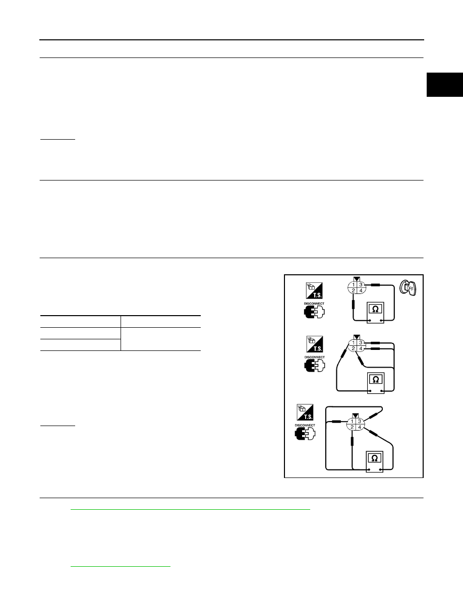
CHECK HEATED OXYGEN SENSOR 2 HEATER

Check the following.

1.

Check resistance between terminals 2 and 3.

2.

Check continuity.

CAUTION:

Discard any heated oxygen sensor which has been dropped
from a height of more than 0.5 m (19.7 in) onto a hard sur-
face such as a concrete floor; use a new one.

Before installing new oxygen sensor, clean exhaust system
threads using Oxygen Sensor Thread Cleaner tool J-43897-
18 or J-43897-12 and approved anti-seize lubricant.

OK or NG

OK

>> GO TO 6.

NG

>> Replace heated oxygen sensor 2.

6. 

CHECK INTERMITTENT INCIDENT

Perform 

EC-120, "TROUBLE DIAGNOSIS FOR INTERMITTENT INCIDENT"

 .

>> INSPECTION END.

Removal and Installation

UBS00D2A

HEATED OXYGEN SENSOR 2

Refer to 

EX-3, "EXHAUST SYSTEM"

 .

Continuity should exist.

Resistance

: 3.3 - 4.0

 [at 25°C (77°F)]

Terminal No.

Continuity

1 and 2, 3, 4

No

4 and 1, 2, 3

SEF221W

EC-136

[KA24DE]

DTC P0101 MAF SENSOR

DTC P0101 MAF SENSOR

PFP:22680

Component Description

UBS00D2B

The mass air flow sensor is placed in the stream of intake air. It mea-
sures the intake flow rate by measuring a part of the entire intake
flow. It consists of a hot wire that is supplied with electric current from
the ECM. The temperature of the hot wire is controlled by the ECM a
certain amount. The heat generated by the hot wire is reduced as
the intake air flows around it. The more air, the greater the heat loss.
Therefore, the ECM must supply more electric current to maintain
the temperature of the hot wire as air flow increases. The ECM
detects the air flow by means of this current change.

CONSULT-II Reference Value in Data Monitor Mode

UBS00D2C

Specification data are reference values.

On Board Diagnosis Logic

UBS00D2D

This self-diagnosis has the one trip detection logic.

SEF893J

MONITOR ITEM

CONDITION

SPECIFICATION

MAS A/F SE-B1

Engine: After warming up

Air conditioner switch: OFF

Shift lever: P or N

No-load

Idle

0.9 - 1.8V

2,500 rpm

1.9 - 2.3V

CAL/LD VALUE

Engine: After warming up

Air conditioner switch: OFF

Shift lever: P or N

No-load

Idle

9.5 - 34.0%

2,500 rpm

13.9 - 24.9%

MASS AIRFLOW

 Engine: After warming up

Air conditioner switch: OFF

Shift lever: P or N

No-load

Idle

0.9 - 5.8 g·m/s

2,500 rpm

7.5 - 13.2 g·m/s

DTC No.

Trouble diagnosis name

DTC detecting condition

Possible cause

P0101

Mass air flow sensor cir-
cuit range/performance 
problem

A)

A high voltage from the sensor is sent to ECM 
under light load driving condition.

Harness or connectors
(The sensor circuit is open or 
shorted.)

Mass air flow sensor

B)

A low voltage from the sensor is sent to ECM 
under heavy load driving condition.

Harness or connectors
(The sensor circuit is open or 
shorted.)

Intake air leaks

Mass air flow sensor

DTC P0101 MAF SENSOR

EC-137

[KA24DE]

C

D

E

F

G

H

I

J

K

L

M

A

EC

DTC Confirmation Procedure

UBS00D2E

Perform “PROCEDURE FOR MALFUNCTION A” first. If the DTC cannot be confirmed, perform “PRO-
CEDURE FOR MALFUNCTION B”.

CAUTION:

Always drive vehicle at a safe speed.

NOTE:
If “DTC Confirmation Procedure” has been previously conducted, always turn ignition switch OFF and wait at
least 5 seconds before conducting the next test. 

PROCEDURE FOR MALFUNCTION A

NOTE:
If engine will not start or stops soon, wait at least 10 seconds with engine stopped (Ignition switch
“ON”) instead of running engine at idle speed.

 With CONSULT-II

1.

Turn ignition switch ON.

2.

Select “DATA MONITOR” mode with CONSULT-II.

3.

Start engine and warm it up to normal operating temperature.

4.

Run engine for at least 10 seconds at idle speed.

5.

If DTC is detected, go to 

EC-140, "Diagnostic Procedure"

 .

 With GST

Follow the procedure “With CONSULT-II”.

PROCEDURE FOR MALFUNCTION B

 With CONSULT-II

1.

Turn ignition switch ON.

2.

Start engine and warm it up to normal operating temperature.
If engine cannot be started, go to 

EC-140, "Diagnostic Procedure"

 .

3.

Select “DATA MONITOR” mode with CONSULT-II.

4.

Check the voltage of “MAS A/F SE-B1” with “DATA MONITOR”.

5.

Increases engine speed to about 4,000 rpm.

6.

Monitor the linear voltage rise in response to engine speed
increases.
If NG, go to 

EC-140, "Diagnostic Procedure"

 .

If OK, go to following step.

SEF174Y

SEF243Y

EC-138

[KA24DE]

DTC P0101 MAF SENSOR

7.

Maintain the following conditions for at least 10 consecutive sec-
onds.

8.

If DTC is detected, go to 

EC-140, "Diagnostic Procedure"

 .

Overall Function Check

UBS00D2F

Use this procedure to check the overall function of the mass air flow sensor circuit. During this check, a DTC
might not be confirmed.

PROCEDURE FOR MALFUNCTION B

 With GST

1.

Start engine and warm it up to normal operating temperature.

2.

Select “MODE 1” with GST.

3.

Check the mass air flow sensor signal with “MODE 1”.

4.

Check for linear mass air flow rise in response to increases to
about 4,000 rpm in engine speed.

5.

If NG, go to 

EC-140, "Diagnostic Procedure"

 .

ENG SPEED

More than 2,000 rpm

THRTL POS SEN

More than 3V

Selector lever

Suitable position

Driving location

Driving vehicle uphill (Increased engine load) will 
help maintain the driving conditions required for 
this test.

SEF175Y

SEF534P


Content   ..  256  257  258  259   ..