Nissan Frontier D22. Manual - part 218
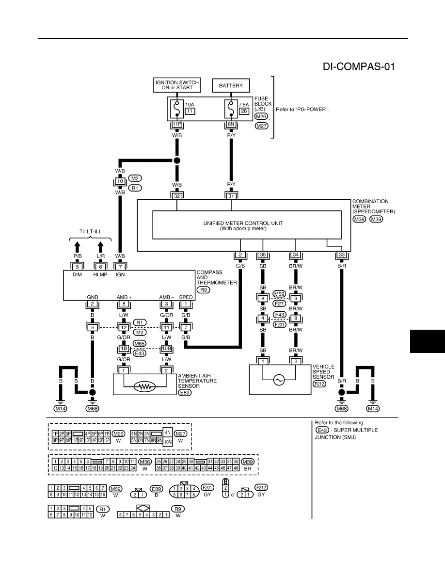
COMPASS AND THERMOMETER
DI-21
C
D
E
F
G
H
I
J
L
M
A
B
DI
Wiring Diagram — COMPAS —
EKS006WC
KING CAB
LKWA0103E
|
|
|
COMPASS AND THERMOMETER DI-21 C D E F G H I J L M A B DI Wiring Diagram — COMPAS — EKS006WC KING CAB LKWA0103E |