Nissan Frontier D22. Manual - part 205


  Index      Nissan     Nissan Frontier D22 Pickup (1998-2004 year) - Service and Repair Manual


Search            


Content   ..  203  204  205  206   ..


Nissan Frontier D22. Manual - part 205


PRECAUTIONS

CO-3

[KA24DE]

C

D

E

F

G

H

I

J

K

L

M

A

CO

PRECAUTIONS

PFP:00001

Precautions for Supplemental Restraint System (SRS) “AIR BAG” and “SEAT 
BELT PRE-TENSIONER”

EBS00GV3

The Supplemental Restraint System such as “AIR BAG” and “SEAT BELT PRE-TENSIONER”, used along
with a front seat belt, helps to reduce the risk or severity of injury to the driver and front passenger for certain
types of collision. This system may include seat belt switch inputs and dual stage front air bag modules. If
equipped with dual stage front air bag modules, the SRS system uses the seat belt switches to determine the
front air bag deployment, and may only deploy one front air bag, depending on the severity of a collision and
whether the front occupants are belted or unbelted. Information necessary to service the system safely is
included in the SRS and SB section of this Service Manual.

The vehicle may be equipped with a passenger air bag deactivation switch. Because no rear seat exists where
a rear-facing child restraint can be placed, the switch is designed to turn off the passenger air bag so that a
rear-facing child restraint can be used in the front passenger seat. The switch is located in the center of the
instrument panel, near the ashtray. When the switch is turned to the ON position, the passenger air bag is
enabled and could inflate for certain types of collision. When the switch is turned to the OFF position, the pas-
senger air bag is disabled and will not inflate. A passenger air bag OFF indicator on the instrument panel lights
up when the passenger air bag is switched OFF. The driver air bag always remains enabled and is not affected
by the passenger air bag deactivation switch.

WARNING:

To avoid rendering the SRS inoperative, which could increase the risk of personal injury or death
in the event of a collision which would result in air bag inflation, all maintenance must be per-
formed by an authorized NISSAN/INFINITI dealer.

Improper maintenance, including incorrect removal and installation of the SRS, can lead to per-
sonal injury caused by unintentional activation of the system. For removal of Spiral Cable and Air
Bag Module, see the SRS section.

Do not use electrical test equipment on any circuit related to the SRS unless instructed to in this
Service Manual. SRS wiring harnesses can be identified by yellow and/or orange harnesses or
harness connectors.

The vehicle may be equipped with a passenger air bag deactivation switch which can be operated
by the customer. When the passenger air bag is switched OFF, the passenger air bag is disabled
and will not inflate. When the passenger air bag is switched ON, the passenger air bag is enabled
and could inflate for certain types of collision. After SRS maintenance or repair, make sure the
passenger air bag deactivation switch is in the same position (ON or OFF) as when the vehicle
arrived for service.

Precautions for Liquid Gasket

EBS00GV4

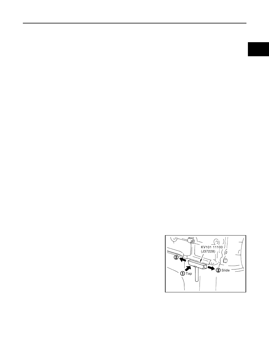
REMOVAL OF LIQUID GASKET

After removing the mounting bolts and nuts, separate the mating
surface using a seal cutter and remove the sealant.     

CAUTION:

Be careful not to damage the mating surfaces.

In areas where the cutter is difficult to use, use a plastic hammer
to lightly tap the areas where the sealant is applied.

CAUTION:

If for some unavoidable reason a tool such as a flat-bladed
screwdriver is used, be careful not to damage the mating sur-
faces.

PBIC0002E

CO-4

[KA24DE]

PRECAUTIONS

LIQUID GASKET APPLICATION PROCEDURE

1.

Using a scraper, remove the old sealant adhering to the mating
surface.

Remove the sealant completely from the groove, mounting
bolts, and bolt holes.

2.

Clean the mating surface thoroughly to remove adhering mois-
ture, grease and foreign materials.

3.

Install the sealant tube into the tube presser.
Use Genuine Silicone RTV or equivalent. Refer to 

GI-42,

"RECOMMENDED CHEMICAL PRODUCTS AND SEAL-
ANTS"

 .

4.

Apply the sealant without breaks to the specified area with the
specified dimensions.

If there is a groove for the sealant application, apply the seal-
ant to the groove.

As for the bolt holes, normally apply the sealant inside the
holes. If specified, it should be applied outside the holes.
Make sure to read the instructions in this manual.

Within five minutes of sealant application, install the mating
component.

If the sealant protrudes, wipe it off immediately.

Do not retighten after the installation.

After 30 minutes or more have passed from the installation, fill
the engine with the correct oil and coolant. Refer to 

MA-12,

"Recommended Fluids and Lubricants"

 .

CAUTION:

If there are specific instructions in the service manual, observe them.

PBIC0003E

EMA0622D

SEM159F

PREPARATION

CO-5

[KA24DE]

C

D

E

F

G

H

I

J

K

L

M

A

CO

PREPARATION

PFP:00002

Special Service Tools

EBS00GV5

The actual shapes of Kent-Moore tools may differ from those of special service tools illustrated here.

Tool number
(Kent-Moore No.)
Tool name

Description

EG17650301
(J33984-A)
Radiator cap tester adapter

Adapting radiator cap tester to radiator filler 
neck
a: 28 (1.10) dia.
b: 31.4 (1.236) dia.
c: 41.3 (1.626) dia.
Unit: mm (in)

WS39930000
(

)

Tube presser

Pressing the tube of liquid gasket

NT564

NT052

CO-6

[KA24DE]

OVERHEATING CAUSE ANALYSIS

OVERHEATING CAUSE ANALYSIS

PFP:00012

Troubleshooting Chart

EBS00GV6

Symptom

Check items

Cooling sys-
tem parts 
malfunction

Poor heat transfer

Water pump malfunction

Worn or loose drive belt

Thermostat stuck closed

Coolant circulation

Damaged fins

Dust contamination or rock 
clogging

Mechanical damage

Clogged radiator cooling 
tube

Excess foreign material 
(rust, dirt, sand, etc.)

Reduced air flow

Fan coupling does not 
operate

Fan and coupling

High resistance to fan rota-
tion

Damaged fan blades

Damaged radiator shroud

Improper coolant mixture 
ratio

Poor coolant quality

Periodic maintenance

Insufficient coolant

Coolant leaks

Cooling hose

Loose clamp

Cracked hose

Water pump

Poor sealing

Radiator cap

Loose

Poor sealing

Radiator

O-ring for damage, deterio-
ration or improper fitting

Cracked radiator tank

Cracked radiator core

Reservoir tank

Cracked reservoir tank

Overflowing reservoir tank

Exhaust gas leaks into 
cooling system

Cylinder head deterioration

Cylinder head gasket dete-
rioration

Except cool-
ing system 
parts mal-
function

Overload on engine

Abusive driving

High engine rpm under no 
load

Driving in low gear for 
extended time

Driving at extremely high 
speed

Powertrain system mal-
function

Installed improper size 
wheels and tires

Dragging brakes

Improper ignition timing

Blocked or restricted air 
flow

Blocked radiator grille

Installed car brassiere

Mud contamination or 
paper clogging

Blocked bumper

Blocked radiator

Blocked condenser

Installed large fog lamp


Content   ..  203  204  205  206   ..