Nissan Frontier D22. Manual - part 165


  Index      Nissan     Nissan Frontier D22 Pickup (1998-2004 year) - Service and Repair Manual


Search            


Content   ..  163  164  165  166   ..


Nissan Frontier D22. Manual - part 165


FRONT DISC BRAKE

BR-27

C

D

E

G

H

I

J

K

L

M

A

B

BR

3.

Bleed air. Refer to 

BR-10, "Bleeding Brake System"

 .

Caliper Disassembly and Assembly

EFS003FX

DISASSEMBLY

WARNING:

Do not place your fingers in front of piston.

CAUTION:

Do not scratch or score cylinder wall.

CL28VD type front disc brake uses plastic pistons. Handle them carefully.

1.

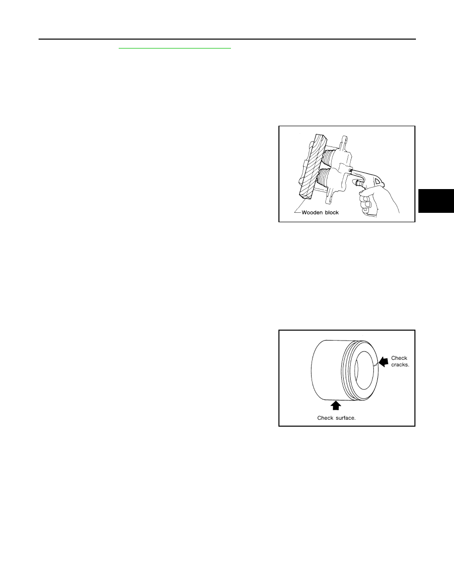
Push out piston and dust covers with compressed air. Use a
wooden block so that both pistons come out evenly.

2.

Remove piston seal with a suitable tool.

INSPECTION AFTER DISASSEMBLY
Cylinder Body

Check inside surface of cylinder for score, rust, wear, damage and presence of foreign objects. If any of
the above conditions are observed, replace cylinder body.

Minor damage from rust or foreign objects may be eliminated by polishing surface with a fine emery paper.
Replace cylinder body if necessary.

CAUTION:

Use brake fluid to clean. Never use mineral oil.

Piston

CAUTION:

Piston sliding surface is plated. Do not polish with emery paper
even if rust or foreign objects are stuck to sliding surface.

Main Pin, Main Pin Bolt and Pin Boot

Check for wear, cracks, rust and other damage. Replace if any of the above conditions are observed.

SBR085A

SBR177C

BR-28

FRONT DISC BRAKE

DISC ROTOR INSPECTION
Runout

1.

Check rotor runout using a dial indicator.

Make sure that wheel bearing axial end play is within the speci-
fications before measuring. Refer to 

FAX-5, "Front Wheel Bear-

ing"

 .

2.

If the rotor runout is out of specification, find minimum rotor
runout position as follows:

a.

Remove nuts and rotor from wheel hub.

b.

Shift the rotor one hole and secure rotor to wheel hub with nuts.

c.

Measure runout.

d.

Repeat steps a. to c. so that minimum rotor runout position can be found.

3.

If the rotor runout is still out of specification, turn rotor with on-car brake lathe (“MAD, DL-8700”, “AMMCO
700 and 705” or equivalent).

Thickness

If thickness variation exceeds the specification, turn rotor with on-car
brake lathe.

ASSEMBLY

1.

Insert piston seal into groove on cylinder body.

2.

With piston boot fitted to piston, insert piston boot into groove on
cylinder body and install piston.

3.

Properly secure piston boot.

CAUTION:

Secure dust seal properly.

Lubricate with new brake fluid before installing pistons
into cylinder body.

Maximum rotor runout

: 0.07 mm (0.0028 in)

SBR089A

Thickness variation (At 
least 8 positions)

: Maximum 0.02 mm 
(0.0008 in)

Rotor repair limit

KA24DE model

: 24.0 mm (0.945 in)

VG33E and VG33ER models

: 26.0 mm (1.024 in)

SBR090A

SBR178C

SBR179CA

FRONT DISC BRAKE

BR-29

C

D

E

G

H

I

J

K

L

M

A

B

BR

Brake Burnishing Procedure

EFS003FY

Burnish the brake contact surfaces according to the following procedure after refinishing or replacing drums or
rotors, after replacing pads or linings, or if a soft pedal occurs at very low mileage.

CAUTION:

Only perform this procedure under safe road and traffic conditions. Use extreme caution.

1.

Drive the vehicle on a straight smooth road at 50 km/h (31 MPH).

2.

Use medium brake pedal/foot effort to bring the vehicle to a complete stop from 50 km/h (31 MPH). Adjust
brake pedal/foot pressure such that vehicle stopping time equals 3 to 5 seconds.

3.

To cool the brake system, drive the vehicle at 50 km/h (31 MPH) for 1 minute without stopping.

4.

Repeat steps 1 to 3, 10 times or more to complete the burnishing procedure.

BR-30

REAR DRUM BRAKE

REAR DRUM BRAKE

PFP:43206

Components

EFS003FZ

1.

Shoe hold pin

2.

Plug

3.

Shoe hold pin

4.

Back plate

5.

Air bleeder cap

6.

Air bleeder

7.

Cylinder body

8.

Piston cup

9.

Piston

10.

Dust cover

11.

Spring

12.

Wheel cylinder

13.

Pin

14. Adjusting lever

15.

Toggle lever

16.

Washer

17. Retainer clip

18.

Retainer spring

19.

Spring seat

20. Shoe hold spring

21.

Retainer

22.

Shoe (leading side)

23. Adjuster

24.

Shoe (trailing side)

WFIA0133E


Content   ..  163  164  165  166   ..