Nissan Frontier D22. Manual - part 159
PRECAUTIONS
BR-3
C
D
E
G
H
I
J
K
L
M
A
B
BR
PRECAUTIONS
PFP:00001
Precautions for Supplemental Restraint System (SRS) “AIR BAG” and “SEAT
BELT PRE-TENSIONER”
EFS003F4
The Supplemental Restraint System such as “AIR BAG” and “SEAT BELT PRE-TENSIONER”, used along
with a front seat belt, helps to reduce the risk or severity of injury to the driver and front passenger for certain
types of collision. This system may include seat belt switch inputs and dual stage front air bag modules. If
equipped with dual stage front air bag modules, the SRS system uses the seat belt switches to determine the
front air bag deployment, and may only deploy one front air bag, depending on the severity of a collision and
whether the front occupants are belted or unbelted. Information necessary to service the system safely is
included in the SRS and SB section of this Service Manual.
The vehicle may be equipped with a passenger air bag deactivation switch. Because no rear seat exists where
a rear-facing child restraint can be placed, the switch is designed to turn off the passenger air bag so that a
rear-facing child restraint can be used in the front passenger seat. The switch is located in the center of the
instrument panel, near the ashtray. When the switch is turned to the ON position, the passenger air bag is
enabled and could inflate for certain types of collision. When the switch is turned to the OFF position, the pas-
senger air bag is disabled and will not inflate. A passenger air bag OFF indicator on the instrument panel lights
up when the passenger air bag is switched OFF. The driver air bag always remains enabled and is not affected
by the passenger air bag deactivation switch.
WARNING:
●
To avoid rendering the SRS inoperative, which could increase the risk of personal injury or death
in the event of a collision which would result in air bag inflation, all maintenance must be per-
formed by an authorized NISSAN/INFINITI dealer.
●
Improper maintenance, including incorrect removal and installation of the SRS, can lead to per-
sonal injury caused by unintentional activation of the system. For removal of Spiral Cable and Air
Bag Module, see the SRS section.
●
Do not use electrical test equipment on any circuit related to the SRS unless instructed to in this
Service Manual. SRS wiring harnesses can be identified by yellow and/or orange harnesses or
harness connectors.
●
The vehicle may be equipped with a passenger air bag deactivation switch which can be operated
by the customer. When the passenger air bag is switched OFF, the passenger air bag is disabled
and will not inflate. When the passenger air bag is switched ON, the passenger air bag is enabled
and could inflate for certain types of collision. After SRS maintenance or repair, make sure the
passenger air bag deactivation switch is in the same position (ON or OFF) as when the vehicle
arrived for service.
Precautions for Brake System
EFS003F5
●
Use brake fluid “DOT 3”.
●
Never reuse drained brake fluid.
●
Be careful not to splash brake fluid on painted areas; it may
cause paint damage. If brake fluid is splashed on painted
areas, wash it away with water immediately.
●
To clean master cylinder parts, disc brake caliper parts or
wheel cylinder parts, use clean brake fluid.
●
Never use mineral oils such as gasoline or kerosene. They
will ruin rubber parts of hydraulic system.
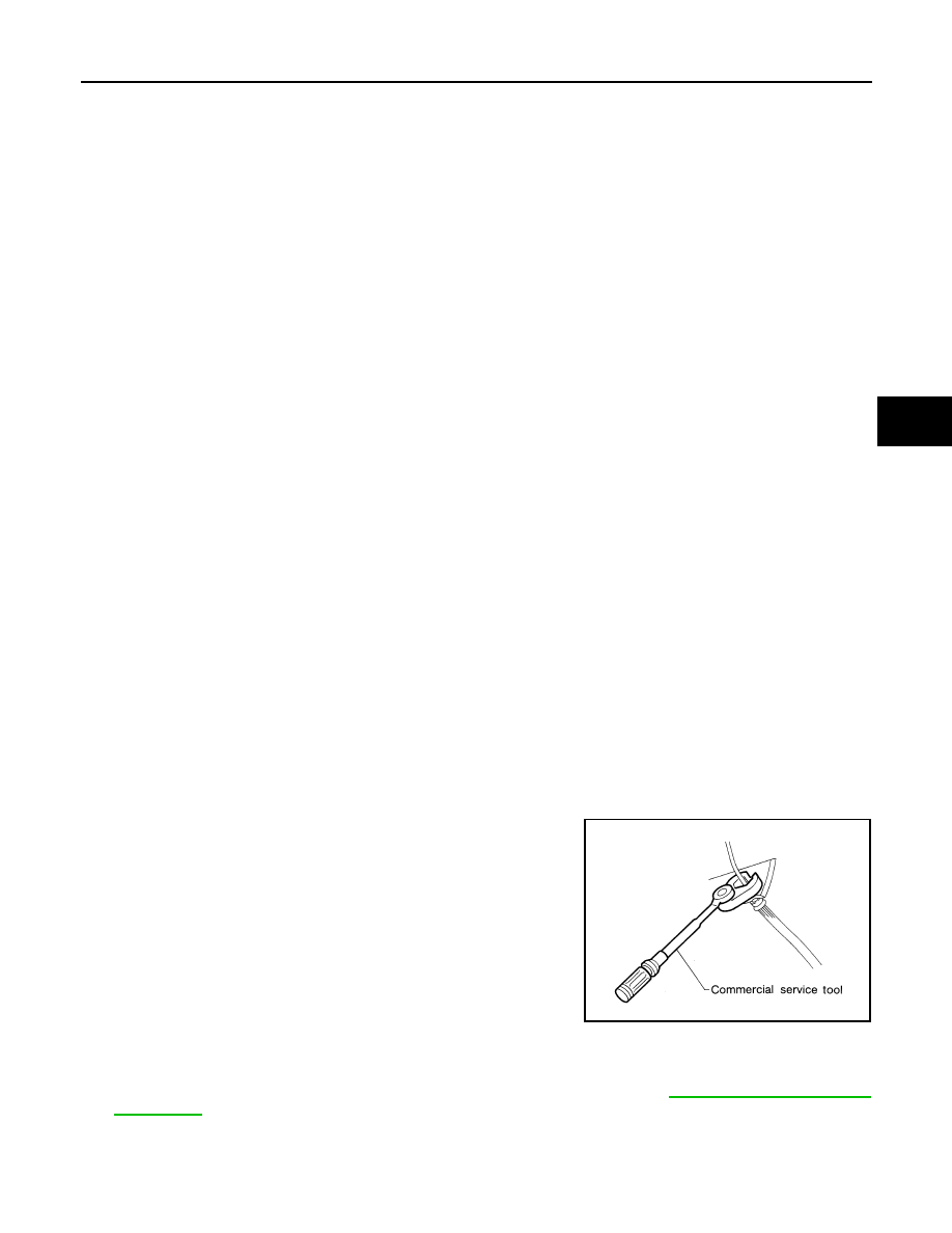
●
Use flare nut wrench when removing and installing brake
tubes.
●
Always torque brake lines when installing.
●
Burnish the brake contact surfaces after refinishing or replacing drums or rotors, after replacing
pads or linings, or if a soft pedal occurs at very low mileage. Refer to
WARNING:
●
Clean brakes with a vacuum dust collector to minimize risk of health hazard from powder caused
by friction.
SBR686C