Nissan Frontier D22. Manual - part 80
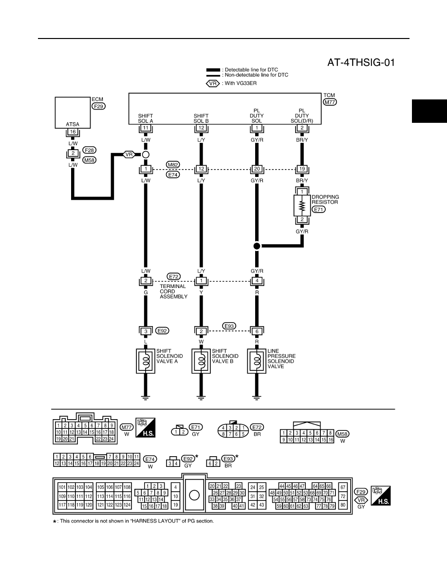
DTC P0734 IMPROPER SHIFTING TO 4TH GEAR POSITION
AT-289
[RE4R01A]
D
E
F
G
H
I
J
K
L
M
A
B
AT
Wiring Diagram — AT — 4TH
ECS007MW
WCWA0152E
|
|
|
DTC P0734 IMPROPER SHIFTING TO 4TH GEAR POSITION AT-289 [RE4R01A] D E F G H I J K L M A B AT Wiring Diagram — AT — 4TH ECS007MW WCWA0152E |