Nissan Frontier D22. Manual - part 74
DTC P0720 VEHICLE SPEED SENSOR·A/T (REVOLUTION SENSOR)
AT-265
[RE4R01A]
D
E
F
G
H
I
J
K
L
M
A
B
AT
3.
CHECK DTC
Perform Diagnostic Trouble Code (DTC) confirmation procedure. Refer to
CODE (DTC) CONFIRMATION PROCEDURE"
OK or NG
OK
>> INSPECTION END
NG
>> 1. Perform TCM input/output signal inspection.
2. If NG, recheck TCM pin terminals for damage or loose connection with harness connector.
Component Inspection
ECS007MF
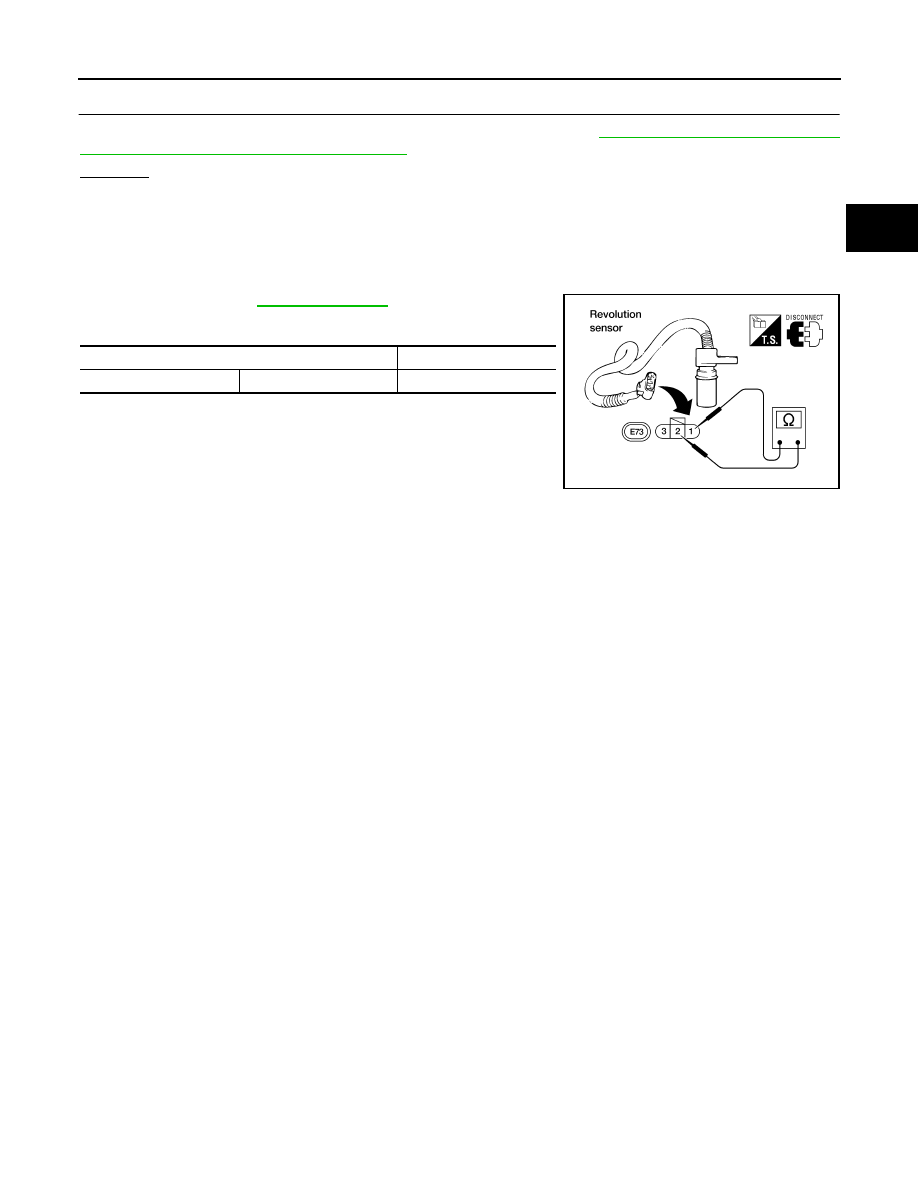
REVOLUTION SENSOR
●
For removal, refer to
.
●
Check resistance between terminals 1 and 2.
Terminal No.
Resistance
1
2
500 - 650
Ω
AAT487A