Nissan Frontier D22. Manual - part 58


  Index      Nissan     Nissan Frontier D22 Pickup (1998-2004 year) - Service and Repair Manual


Search            


Content   ..  56  57  58  59   ..


Nissan Frontier D22. Manual - part 58


ON BOARD DIAGNOSTIC SYSTEM DESCRIPTION

AT-201

[RE4R01A]

D

E

F

G

H

I

J

K

L

M

A

B

AT

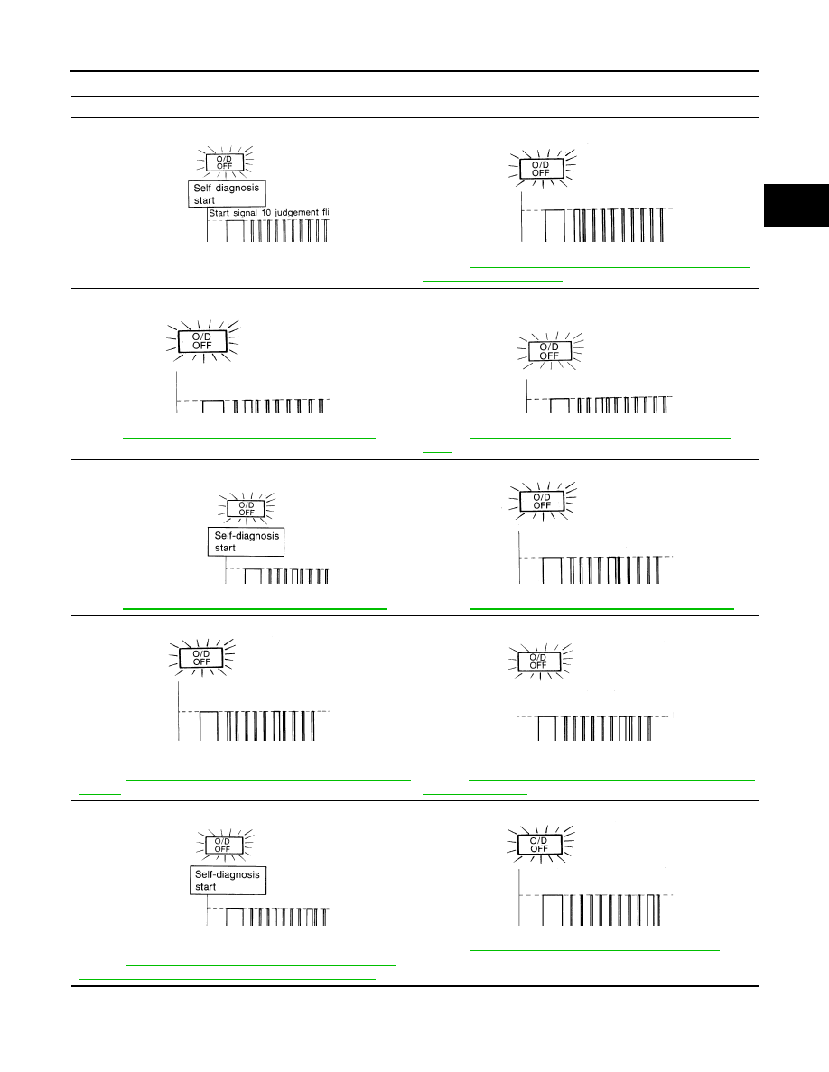
JUDGEMENT OF SELF-DIAGNOSIS CODE (VG33E ONLY)

O/D OFF indicator lamp:

All judgement flickers are same.

All circuits that can be confirmed by self-diagnosis are OK.

1st judgement flicker is longer than others.

Revolution sensor circuit is short-circuited or disconnected.
Þ Go to 

AT-261, "DTC P0720 VEHICLE SPEED SENSOR·A/T 

(REVOLUTION SENSOR)"

 .

2nd judgement flicker is longer than others.

Vehicle speed sensor circuit is short-circuited or disconnected.
Þ Go to

AT-340, "DTC VEHICLE SPEED SENSOR·MTR"

 .

3rd judgement flicker is longer than others.

Throttle position sensor circuit is short-circuited or disconnected.
Þ Go to 

AT-321, "DTC P1705 THROTTLE POSITION SEN-

SOR"

 .

4th judgement flicker is longer than others.

Shift solenoid valve A circuit is short-circuited or disconnected.
Þ Go to

AT-311, "DTC P0750 SHIFT SOLENOID VALVE A"

 .

5th judgement flicker is longer than others.

Shift solenoid valve B circuit is short-circuited or disconnected.
Þ Go to 

AT-316, "DTC P0755 SHIFT SOLENOID VALVE B"

 .

6th judgement flicker is longer than others.

Overrun clutch solenoid valve circuit is short-circuited or discon-
nected.
Þ Go to 

AT-329, "DTC P1760 OVERRUN CLUTCH SOLENOID 

VALVE"

 .

7th judgement flicker is longer than others.

Torque converter clutch solenoid valve circuit is short-circuited or 
disconnected.
Þ Go to 

AT-293, "DTC P0740 TORQUE CONVERTER CLUTCH 

SOLENOID VALVE"

 .

8th judgement flicker is longer than others.

A/T fluid temperature sensor is disconnected or TCM power 
source circuit is damaged.
Þ Go to 

AT-334, "DTC BATT/FLUID TEMP SEN (A/T FLUID 

TEMP SENSOR CIRCUIT AND TCM POWER SOURCE)"

 .

9th judgement flicker is longer than others.

Engine speed signal circuit is short-circuited or disconnected.
Þ Go to 

AT-266, "DTC P0725 ENGINE SPEED SIGNAL"

 .

SAT436F

SAT437F

SAT439F

SAT441F

SAT443F

SAT445F

SAT447F

SAT449F

SAT451F

SAT453F

AT-202

[RE4R01A]

ON BOARD DIAGNOSTIC SYSTEM DESCRIPTION

t

1

  = 2.5 seconds

t

2

  = 2.0 seconds

t

3

  = 1.0 second

t

4

  = 1.0 second

JUDGEMENT OF SELF-DIAGNOSIS CODE (VG33ER ONLY)

10th judgement flicker is longer than others.

Line pressure solenoid valve circuit is short-circuited or discon-
nected.
Þ Go to 

AT-306, "DTC P0745 LINE PRESSURE SOLENOID 

VALVE"

 .

Flickers as shown below.

Battery power is low.
Battery has been disconnected for a long time.
Battery is connected conversely.
(When reconnecting TCM connectors. — This is not a problem.)

Lamp comes on.

PNP switch, overdrive control switch or throttle position switch cir-
cuit is disconnected or TCM is damaged.
Þ Go to 

AT-387, "21. TCM Self-diagnosis Does Not Activate 

(PNP, Overdrive Control and Throttle Position Switches Cir-
cuit Checks)"

 .

O/D OFF indicator lamp:

SAT455F

SAT457F

SAT367J

O/D OFF indicator lamp:

All judgement flickers are same.

All circuits that can be confirmed by self-diagnosis are OK.

1st judgement flicker is longer than others.

Revolution sensor circuit is short-circuited or disconnected.
Þ Go to 

AT-261, "DTC P0720 VEHICLE SPEED SENSOR·A/T 

(REVOLUTION SENSOR)"

 .

2nd judgement flicker is longer than others.

Vehicle speed sensor circuit is short-circuited or disconnected.
Þ Go to 

AT-340, "DTC VEHICLE SPEED SENSOR·MTR"

 .

3rd judgement flicker is longer than others.

Throttle position sensor circuit is short-circuited or disconnected.
Þ Go to 

AT-321, "DTC P1705 THROTTLE POSITION SEN-

SOR"

 .

LAT425

LAT426

LAT427

LAT428

ON BOARD DIAGNOSTIC SYSTEM DESCRIPTION

AT-203

[RE4R01A]

D

E

F

G

H

I

J

K

L

M

A

B

AT

t

1

  = 2.5 seconds

t

2

  = 2.0 seconds

t

3

  = 1.0 second

t

4

  = 1.0 second

4th judgement flicker is longer than others.

Shift solenoid valve A circuit is short-circuited or disconnected.
Þ Go to 

AT-311, "DTC P0750 SHIFT SOLENOID VALVE A"

 .

5th judgement flicker is longer than others.

Shift solenoid valve B circuit is short-circuited or disconnected.
Þ Go to 

AT-316, "DTC P0755 SHIFT SOLENOID VALVE B"

 .

6th judgement flicker is longer than others.

Overrun clutch solenoid valve circuit is short-circuited or discon-
nected.
Þ Go to 

AT-329, "DTC P1760 OVERRUN CLUTCH SOLENOID 

VALVE"

 .

7th judgement flicker is longer than others.

Torque converter clutch solenoid valve circuit is short-circuited or 
disconnected.
Þ Go to 

AT-293, "DTC P0740 TORQUE CONVERTER CLUTCH 

SOLENOID VALVE"

 .

8th judgement flicker is longer than others.

A/T fluid temperature sensor is disconnected or TCM power 
source circuit is damaged.
Þ Go to 

AT-334, "DTC BATT/FLUID TEMP SEN (A/T FLUID 

TEMP SENSOR CIRCUIT AND TCM POWER SOURCE)"

 .

9th judgement flicker is longer than others.

Engine speed signal circuit is short-circuited or disconnected.
Þ Go to 

AT-266, "DTC P0725 ENGINE SPEED SIGNAL"

 .

10th judgement flicker is longer than others.

Þ Go to 

AT-344, "DTC TURBINE REVOLUTION SENSOR 

(VG33ER ONLY)"

 .

11th judgement flicker is longer than others.

Line pressure solenoid valve circuit is short-circuited or discon-
nected.
Þ Go to 

AT-306, "DTC P0745 LINE PRESSURE SOLENOID 

VALVE"

 .

Flickers as shown below.

Battery power is low.
Battery has been disconnected for a long time.
Battery is connected conversely.
(When reconnecting TCM connectors. — This is not a problem.)

Lamp comes on.

PNP switch, overdrive control switch or throttle position switch cir-
cuit is disconnected or TCM is damaged.
Þ Go to 

AT-387, "21. TCM Self-diagnosis Does Not Activate 

(PNP, Overdrive Control and Throttle Position Switches Cir-
cuit Checks)"

 .

O/D OFF indicator lamp:

LAT429

LAT430

LAT431

LAT432

LAT433

LAT434

LAT435

SAT455F

SAT457F

SAT367J

AT-204

[RE4R01A]

TROUBLE DIAGNOSIS — INTRODUCTION

TROUBLE DIAGNOSIS — INTRODUCTION

PFP:00000

Introduction

ECS007LU

The TCM receives a signal from the vehicle speed sensor, throttle
position sensor or PNP switch and provides shift control or lock-up
control via A/T solenoid valves.
The TCM also communicates with the ECM by means of a signal
sent from sensing elements used with the OBD-related parts of the
A/T system for malfunction-diagnostic purposes. The TCM is capa-
ble of diagnosing malfunctioning parts while the ECM can store mal-
functions in its memory.
Input and output signals must always be correct and stable in the
operation of the A/T system. The A/T system must be in good oper-
ating condition and be free of valve seizure, solenoid valve malfunc-
tion, etc.
It is much more difficult to diagnose a problem that occurs intermit-
tently rather than continuously. Most intermittent problems are
caused by poor electric connections or improper wiring. In this case,
careful checking of suspected circuits may help prevent the replace-
ment of good parts.
A visual check only may not find the cause of the problems. A road
test with CONSULT-II (or GST) or a circuit tester connected should
be performed. Follow the “Work Flow”. Refer to 

AT-208, "Work Flow"

.
Before undertaking actual checks, take a few minutes to talk with a
customer who approaches with a driveability complaint. The cus-
tomer can supply good information about such problems, especially
intermittent ones. Find out what symptoms are present and under what conditions they occur. A “Diagnostic
Worksheet” should be used. Refer to 

AT-205, "DIAGNOSTIC WORKSHEET"

 .

Start your diagnosis by looking for “conventional” problems first. This
will help troubleshoot driveability problems on an electronically con-
trolled engine vehicle.
Also check related Service bulletins.

AAT473A

SAT632I

SEF234G


Content   ..  56  57  58  59   ..