Nissan Frontier D22. Manual - part 13
OVERALL SYSTEM
AT-21
[RL4R01A]
D
E
F
G
H
I
J
K
L
M
A
B
AT
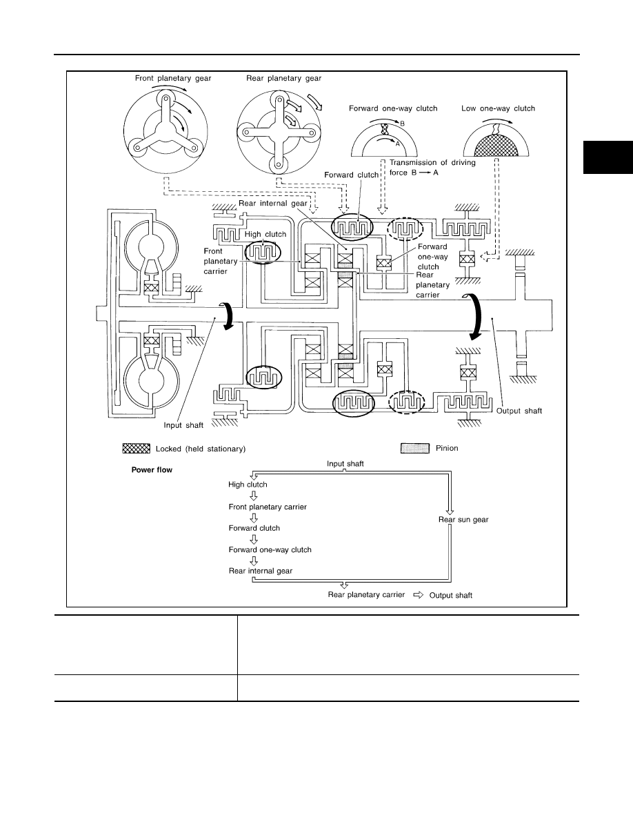
“D
3
” Position
SAT098J
●
High clutch
●
Forward clutch
●
Forward one-way clutch
Input power is transmitted to front planetary carrier through high clutch. And front plan-
etary carrier is connected to rear internal gear by operation of forward clutch and for-
ward one-way clutch.
This rear internal gear rotation and another input (the rear sun gear) accompany rear
planetary carrier to turn at the same speed.
Overrun clutch
engagement conditions
D
3
: Overdrive control switch “OFF” and throttle opening is less than 3/16
Throttle opening less than 3/16