Nissan Xterra. Manual - part 526
PCS
POWER CONSUMPTION CONTROL SYSTEM
PCS-7
< SYSTEM DESCRIPTION >
[IPDM E/R]
C
D
E
F
G
H
I
J
K
L
B
A
O
P
N
POWER CONSUMPTION CONTROL SYSTEM
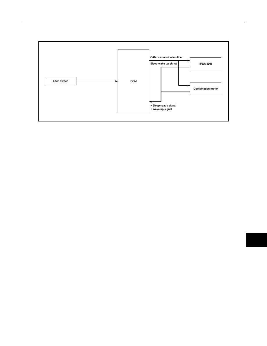
System Diagram
INFOID:0000000009483717
System Description
INFOID:0000000009483718
OUTLINE
• IPDM E/R incorporates a power consumption control function that reduces the power consumption accord-
ing to the vehicle status.
• IPDM E/R changes its status (control mode) with the sleep wake up signal received from BCM via CAN com-
munication.
Normal mode (wake-up)
- CAN communication is normally performed with other control units.
- Individual unit control by IPDM E/R is normally performed.
Low power consumption mode (sleep)
- Low power consumption control is active.
- CAN transmission is stopped.
SLEEP MODE ACTIVATION
• IPDM E/R judges that the sleep-ready conditions are fulfilled when the ignition switch is OFF and none of the
conditions below are present. Then it transmits a sleep-ready signal (ready) to BCM via CAN communica-
tion.
- Front wiper fail-safe operation
- Outputting signals to actuators
- Switches or relays operating
- Auto active test is starting
- Emergency OFF
- Output requests are being received from control units via CAN communication.
• IPDM E/R stops CAN communication and enters the low power consumption mode when it receives a sleep
wake up signal (sleep) from BCM and the sleep-ready conditions are fulfilled.
WAKE-UP OPERATION
• IPDM E/R changes from the low power consumption mode to the normal mode when it receives a sleep
wake-up signal (wake up) from BCM or any of the following conditions is fulfilled. In addition, it transmits a
sleep-ready signal (not-ready) to BCM via CAN communication to report the CAN communication start.
- Ignition switch ON
- An output request is received from a control unit via CAN communication.
ALCIA0030GB