Nissan Xterra. Manual - part 501


  Index      Nissan     Nissan Xterra (2014 year) - Service and Repair Manual


Search            


Content   ..  499  500  501  502   ..


Nissan Xterra. Manual - part 501


CHASSIS AND BODY MAINTENANCE

MA-29

< PERIODIC MAINTENANCE >

C

D

E

F

G

H

I

J

K

L

M

B

MA

N

O

A

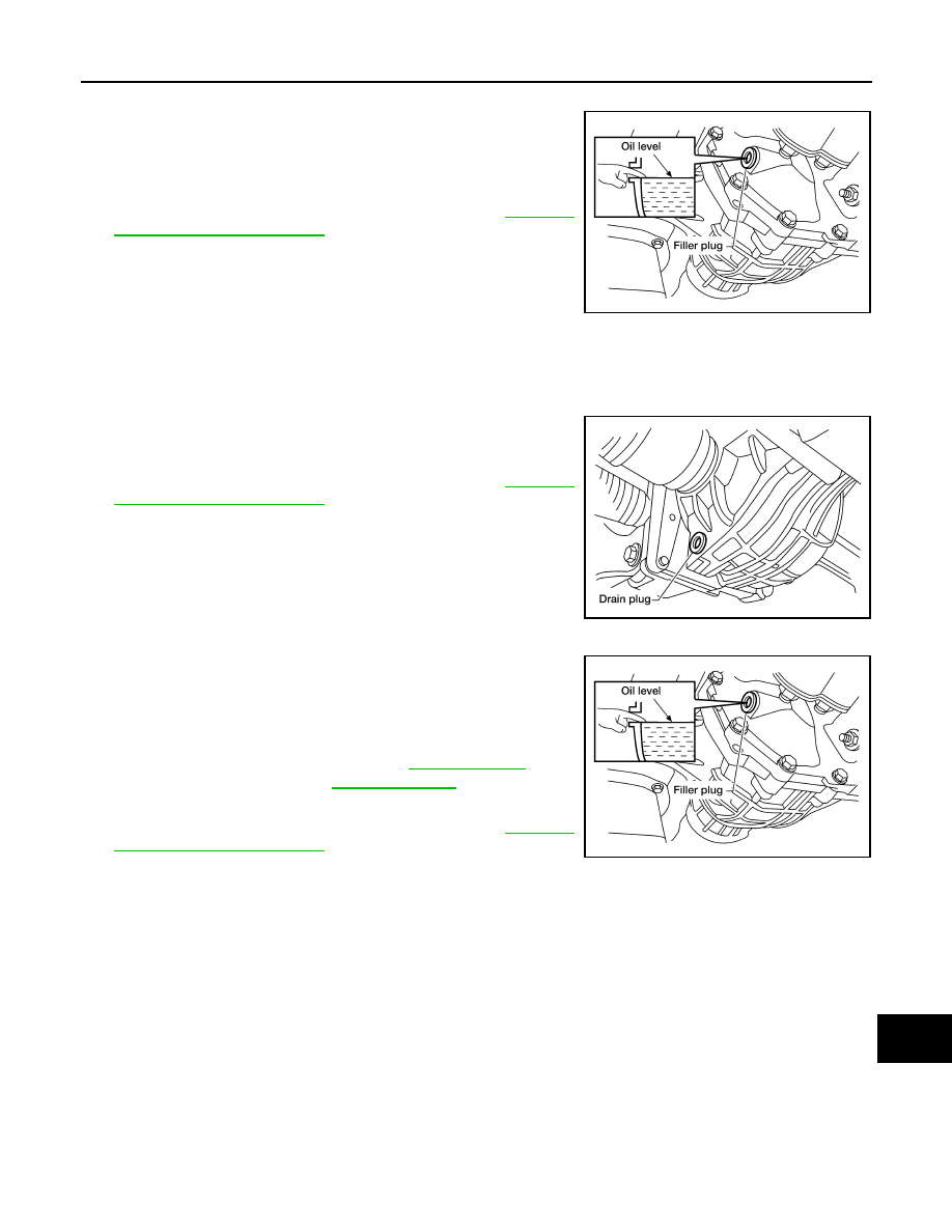
1. Make sure that differential gear oil is not leaking from the front final drive assembly or around it.
2. Check the differential gear oil level from the filler plug hole as

shown.

CAUTION:

Do not start engine while checking differential gear oil level.

3. Install the filler plug with a new gasket on it to the front final drive

assembly. Tighten to the specified torque. Refer to 

DLN-167,

"Disassembly and Assembly"

.

CAUTION:

Do not reuse gasket.

DIFFERENTIAL GEAR OIL : Changing Front Final Drive Oil (R180A)

INFOID:0000000009484289

DRAINING

1. Stop the engine.
2. Remove the drain plug and gasket from the front final drive

assembly to drain the differential gear oil.

3. Install the drain plug with a new gasket to the front final drive

assembly. Tighten to the specified torque. Refer to 

DLN-167,

"Disassembly and Assembly"

.

CAUTION:

Do not reuse gasket.

FILLING

1. Remove the filler plug and gasket from the front final drive

assembly.

2. Fill the front final drive assembly with new differential gear oil

until the level reaches the specified level near the filler plug hole.

3. Install the filler plug with a new gasket on it to the front final drive

assembly. Tighten to the specified torque. Refer to 

DLN-167,

"Disassembly and Assembly"

.

CAUTION:

Do not reuse gasket.

DIFFERENTIAL GEAR OIL : Checking Rear Final Drive Oil (C200)

INFOID:0000000009484290

DIFFERENTIAL GEAR OIL LEAKAGE AND LEVEL

1. Make sure that differential gear oil is not leaking from the rear final drive assembly or around it.

LDIA0176E

LDIA0175E

Differential gear oil 
grade and capacity

: Refer to 

MA-12, "Fluids 

and Lubricants"

.

LDIA0176E

MA-30

< PERIODIC MAINTENANCE >

CHASSIS AND BODY MAINTENANCE

2. Check the differential gear oil level from the filler plug hole as

shown.

CAUTION:

Do not start engine while checking differential gear oil level.

3. Install the filler plug with sealant applied on the threads to the

rear final drive assembly. Tighten to the specified torque. Refer

to 

DLN-199, "Disassembly and Assembly"

.

• Use High Performance Thread Sealant or equivalent. Refer to

GI-21, "Recommended Chemical Products and Sealants"

.

DIFFERENTIAL GEAR OIL : Changing Rear Final Drive Oil (C200)

INFOID:0000000009484291

DRAINING

1. Stop engine.
2. Remove the drain plug from the rear final drive assembly to

drain the differential gear oil.

3. Install the drain plug with a new gasket to the rear final drive

assembly. Tighten to the specified torque. Refer to 

DLN-199,

"Disassembly and Assembly"

CAUTION:

Do not reuse gasket.

FILLING

1. Remove the filler plug from the rear final drive assembly.
2. Fill the rear final drive assembly with new differential gear oil

until the level reaches the specified level near the filler plug hole.

3. Install the filler plug with sealant applied on the threads to the

rear final drive assembly. Tighten to the specified torque. Refer

to  

DLN-199, "Disassembly and Assembly"

.

• Use High Performance Thread Sealant or equivalent. Refer to

GI-21, "Recommended Chemical Products and Sealants"

.

DIFFERENTIAL GEAR OIL : Checking Rear Final Drive Oil (M226)

INFOID:0000000009484292

DIFFERENTIAL GEAR OIL LEAKAGE AND LEVEL

1. Make sure that differential gear oil is not leaking from the rear final drive assembly or around it.
2. Check the differential gear oil level from the filler plug hole as

shown.

CAUTION:

Do not start engine while checking differential gear oil level.

3. Install the filler plug with sealant applied on the threads to the

rear final drive assembly. Tighten to the specified torque. Refer

to 

DLN-230, "Disassembly and Assembly"

.

• Use High Performance Thread Sealant or equivalent. Refer to

GI-21, "Recommended Chemical Products and Sealants"

.

LDIA0127E

LDIA0187E

Differential gear oil 
grade and capacity

: Refer to 

MA-12, "Fluids 

and Lubricants"

.

LDIA0127E

LDIA0127E

CHASSIS AND BODY MAINTENANCE

MA-31

< PERIODIC MAINTENANCE >

C

D

E

F

G

H

I

J

K

L

M

B

MA

N

O

A

DIFFERENTIAL GEAR OIL : Changing Rear Final Drive Oil (M226)

INFOID:0000000009484293

DRAINING

1. Stop engine.
2. Remove the drain plug from the rear final drive assembly to

drain the differential gear oil.

3. Install the drain plug with sealant applied on the threads to the

rear final drive assembly. Tighten to the specified torque. Refer

to 

DLN-230, "Disassembly and Assembly"

.

• Use High Performance Thread Sealant or equivalent. Refer to

GI-21, "Recommended Chemical Products and Sealants"

FILLING

1. Remove the filler plug from the rear final drive assembly.
2. Fill the rear final drive assembly with new differential gear oil

until the level reaches the specified level near the filler plug hole.

3. Install the filler plug with sealant applied on the threads to the

rear final drive assembly. Tighten to the specified torque. Refer

to 

DLN-230, "Disassembly and Assembly"

.

• Use High Performance Thread Sealant or equivalent. Refer to

GI-21, "Recommended Chemical Products and Sealants"

.

WHEELS
WHEELS : Adjustment

INFOID:0000000009484294

BALANCING WHEELS (ADHESIVE WEIGHT TYPE)

Preparation Before Adjustment

Remove inner and outer balance weights from the road wheel using releasing agent, remove double-faced

adhesive tape from the road wheel.

CAUTION:

• Be careful not to scratch the road wheel during removal.

• After removing double-faced adhesive tape, wipe clean all traces of releasing agent from the road

wheel.

Wheel Balance Adjustment

• If a balancer machine has an adhesive weight mode setting, select the adhesive weight mode setting and

skip Step 2. below. If a balancer machine only has the clip-on (rim flange) weight mode setting, follow Step 2.

to calculate the correct size adhesive weight.

1. Set road wheel on balancer machine using the center hole as a guide. Start the balancer machine.
2. For balancer machines that only have a clip-on (rim flange) weight mode setting, follow this step to calcu-

late the correct size adhesive weight to use. When inner and outer imbalance values are shown on the

balancer machine indicator, multiply outer imbalance value by 5/3 (1.67) to determine balance weight that

should be used. Select the outer balance weight with a value closest to the calculated value above and

install in to the designated outer position of, or at the designated angle in relation to the road wheel.

LDIA0183E

Differential gear oil 
grade and capacity

: Refer to 

MA-12, "Fluids 

and Lubricants"

.

LDIA0127E

MA-32

< PERIODIC MAINTENANCE >

CHASSIS AND BODY MAINTENANCE

a. Indicated imbalance value 

× 5/3 = balance weight to be installed

Calculation example:

23 g (0.81 oz) 

× 5/3 (1.67) = 38.33 g (1.35 oz) ⇒ 40 g (1.41 oz)

balance weight (closer to calculated balance weight value)

NOTE:

Note that balance weight value must be closer to the calculated

balance weight value.

Example:

37.4 

⇒ 35 g (1.23 oz)

37.5 

⇒ 40 g (1.41 oz)

3. Install balance weight in the position shown.

CAUTION:

• Do not install the inner balance weight before installing

the outer balance weight.

• Before installing the balance weight, be sure to clean the

mating surface of the road wheel.

• When installing balance weight (1) to road wheel, set it into the

grooved area (A) on the inner wall of the road wheel as shown

so that the balance weight center (B) is aligned with the bal-

ancer machine indication position (angle) (C).

CAUTION:

• Always use Genuine NISSAN adhesive balance weights.

• Balance weights are non-reusable; always replace with

new ones.

• Do not install more than three sheets of balance weight.

4. If calculated balance weight value exceeds 50 g (1.76 oz), install

two balance weight sheets in line with each other as shown.

CAUTION:

Do not install one balance weight sheet on top another.

5. Start balancer machine again.
6. Install balance weight on inner side of road wheel in the bal-

ancer machine indication position (angle).

CAUTION:

Do not install more than two balance weights.

7. Start balancer machine. Make sure that inner and outer residual

imbalance values are 5 g (0.17 oz) each or below.

8. If either residual imbalance value exceeds 5 g (0.17 oz), repeat installation procedures.

TIRE ROTATION

SMA054D

JPEIC0040ZZ

Wheel balance

Dynamic (At flange)

Static (At flange)

Maximum allowable im-
balance

Refer to 

WT-53, "Road Wheel"

.

PEIA0033E


Content   ..  499  500  501  502   ..