Nissan Xterra. Manual - part 498


  Index      Nissan     Nissan Xterra (2014 year) - Service and Repair Manual


Search            


Content   ..  496  497  498  499   ..


Nissan Xterra. Manual - part 498


ENGINE MAINTENANCE

MA-17

< PERIODIC MAINTENANCE >

C

D

E

F

G

H

I

J

K

L

M

B

MA

N

O

A

CAUTION:

The compressed air supply must be equipped with an air dryer.

7. The vacuum gauge will begin to rise and there will be an audible hissing noise. During this process open

the ball valve on the refill hose slightly. Coolant will be visible rising in the refill hose. Once the refill hose is

full of coolant, close the ball valve. This will purge any air trapped in the refill hose.

8. Continue to draw the vacuum until the gauge reaches 28 inches

of vacuum. The gauge may not reach 28 inches in high altitude

locations, use the vacuum specifications based on the altitude

above sea level.

9. When the vacuum gauge has reached the specified amount, disconnect the air hose and wait 20 seconds

to see if the system loses any vacuum. If the vacuum level drops, perform any necessary repairs to the

system and repeat steps 6 - 8 to bring the vacuum to the specified amount. Recheck for any leaks. 

10. Place the coolant container (with the refill hose inserted) at the same level as the top of the radiator. Then

open the ball valve on the refill hose so the coolant will be drawn up to fill the cooling system. The cooling

system is full when the vacuum gauge reads zero.

CAUTION:

Do not allow the coolant container to get too low when filling, to avoid air from being drawn into

the cooling system. 

11. Remove the Tool from the radiator neck opening and install the radiator cap.
12. Remove the non-vented reservoir cap.
13. Fill the cooling system reservoir tank to the specified level. Run the engine to warm up the cooling system

and top up the system as necessary before installing the vented reservoir cap.

14. Install the engine under cover. Refer to 

EXT-15, "Removal and Installation"

.

FUEL LINES
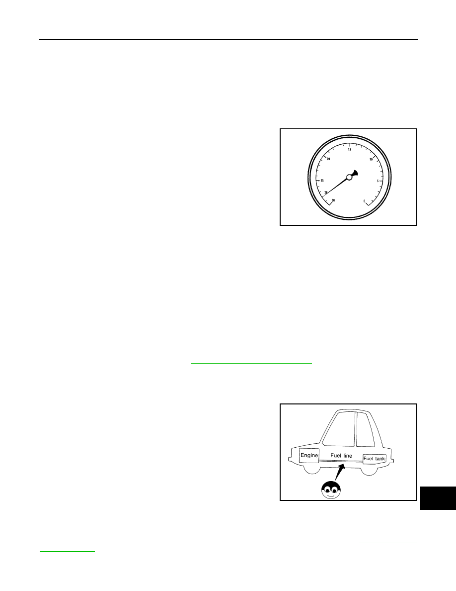
FUEL LINES : Checking Fuel Line

INFOID:0000000009484269

Inspect fuel lines, fuel filler cap and fuel tank for improper attach-

ment, leaks, cracks, damage, loose connections, chafing or deterio-

ration.

If necessary, repair or replace damaged parts.

FUEL FILTER
FUEL FILTER : Changing Fuel Filter

INFOID:0000000009484270

The fuel filter is part of the fuel level sensor unit, fuel filter and fuel pump assembly. Refer to 

FL-11, "Removal

and Installation"

.

WARNING:

Compressed air 
supply pressure

: 549 - 824 kPa (5.6 - 8.4 kg/cm

2

80 - 119 psi)

Altitude above sea level

Vacuum gauge reading

0 - 100 m (328 ft)

: 28 inches of vacuum

300 m (984 ft)

: 27 inches of vacuum

500 m (1,641 ft)

: 26 inches of vacuum

1,000 m (3,281 ft)

: 24 - 25 inches of vacuum

LLIA0057E

SMA803A

MA-18

< PERIODIC MAINTENANCE >

ENGINE MAINTENANCE

Before replacing the fuel filter, release the fuel pressure from the fuel system. Refer to 

EC-494, "Fuel

Pressure Check"

.

AIR CLEANER FILTER
AIR CLEANER FILTER : Exploded View

INFOID:0000000009484271

AIR CLEANER FILTER : Removal and Installation

INFOID:0000000009484272

REMOVAL

1. Remove the engine room cover (if equipped).
2. Disconnect air duct and resonator from the air cleaner case (upper).
3. Disconnect MAF/IAT sensor.
4. Unhook clips, and lift air cleaner case (upper).
5. Remove air cleaner filter.

INSTALLATION

Installation is in the reverse order of removal.

ENGINE OIL
ENGINE OIL : Inspection

INFOID:0000000009484273

OIL LEVEL

• Before starting the engine make sure the vehicle is parked on a flat

and level surface, then check the oil level. If the engine is already

running, turn it off and allow 10 minutes before checking.

• Pull out oil level gauge and wipe clean.

• Insert oil level gauge.

• Check that the oil level is within the low (L) and high (H) range as

indicated on the dipstick.

• If the engine oil level is out of range, add oil as necessary. Refer to

MA-12, "Fluids and Lubricants"

.

CAUTION:

Do not overfill the engine with oil.

1.

Air cleaner case (lower)

2.

Air cleaner filter

3.

Air cleaner case (upper)

4.

Air duct and resonator

5.

MAF/IAT sensor

Front

AWBIA1074GB

PBIC2823E

ENGINE MAINTENANCE

MA-19

< PERIODIC MAINTENANCE >

C

D

E

F

G

H

I

J

K

L

M

B

MA

N

O

A

ENGINE OIL : Changing Engine Oil

INFOID:0000000009484274

WARNING:

• Be careful not to burn yourself, as the engine and engine oil may be hot.

• Prolonged and repeated contact with used engine oil may cause skin cancer; try to avoid direct skin

contact with used oil. If skin contact is made, wash thoroughly with soap or hand cleaner as soon as

possible.

1. Warm up the engine, and check for any oil leaks.
2. Stop the engine and wait for at least 10 minutes.
3. Remove the oil drain plug and oil filler cap to drain the old oil.
4. Install a new washer on the oil drain plug, then install the oil drain plug in the oil pan.

CAUTION:

• Clean the drain plug.

• Do not reuse copper sealing washer.

5. Refill the engine with new specified engine oil.

CAUTION:

The refill capacity depends on the oil temperature and drain time. Use the “Refill oil capacity” val-

ues as a reference and check the oil level using the dipstick when filling the engine with oil.

6. Warm up the engine and check the area around the drain plug and oil filter for any oil leaks.
7. Stop the engine and wait for more than 10 minutes.
8. Check the oil level using the dipstick as shown. Add oil as nec-

essary and install the oil filler cap. Refer to 

MA-18, "ENGINE

OIL : Inspection"

.

CAUTION:

Do not overfill the engine with oil.

OIL FILTER
OIL FILTER : Removal and Installation

INFOID:0000000009484275

REMOVAL

1. Remove the engine under cover acess door. Refer to 

EXT-15, "Removal and Installation"

.

2. Drain engine oil. Refer to 

LU-8, "Changing Engine Oil"

.

3. Remove the oil filter using Tool as shown.

WARNING:

Be careful not to burn yourself, as the engine and engine oil

may be hot.

CAUTION:

• Oil filter is equipped with a pressure relief valve. 

• Use Genuine NISSAN Oil Filter or equivalent.

• When removing, prepare a shop cloth to absorb any

engine oil leaks or spills.

Oil drain plug

: Refer to 

EM-34, "Removal and Installation"

.

Oil grade and viscosity

: Refer to 

MA-12, "Fluids and Lubricants"

.

Oil capacity

: Refer to 

MA-12, "Fluids and Lubricants"

.

PBIC2823E

Tool number

: KV10115801 (J-38956)

LBIA0425E

MA-20

< PERIODIC MAINTENANCE >

ENGINE MAINTENANCE

• Do not allow engine oil to adhere to drive belts.

• Completely wipe off any engine oil that adheres to the engine and the vehicle.

INSTALLATION

1. Remove foreign materials adhering to the oil filter seal mating surface.
2. Apply clean engine oil to the oil filter seal circumference of the

new oil filter as shown.

3. Screw on the oil filter manually until it touches the installation

surface, then tighten it by 2/3 turn as shown. Or tighten to speci-

fication.

4. Refill engine with new engine oil. Refer to 

LU-8, "Changing Engine Oil"

.

5. Inspect the engine for oil leaks. Refer to 

MA-19, "OIL FILTER : Removal and Installation"

.

6. Install the engine under cover acess door. Refer to 

EXT-15, "Removal and Installation"

.

INSPECTION AFTER INSTALLATION

1. Check the engine oil level. Refer to 

LU-7, "Inspection"

.

2. Start the engine and check for engine oil leaks.
3. Stop the engine and wait for 10 minutes.
4. Check the engine oil level and add engine oil as required.

SPARK PLUG

SMA010

Oil filter

: 17.7 N·m (1.8 kg-m, 13 ft-lb)

SMA702C


Content   ..  496  497  498  499   ..