Nissan Xterra. Manual - part 460
HAC-38
< DTC/CIRCUIT DIAGNOSIS >
[MANUAL AIR CONDITIONER]
INTAKE SENSOR
INTAKE SENSOR
System Description
INFOID:0000000009482484
COMPONENT DESCRIPTION
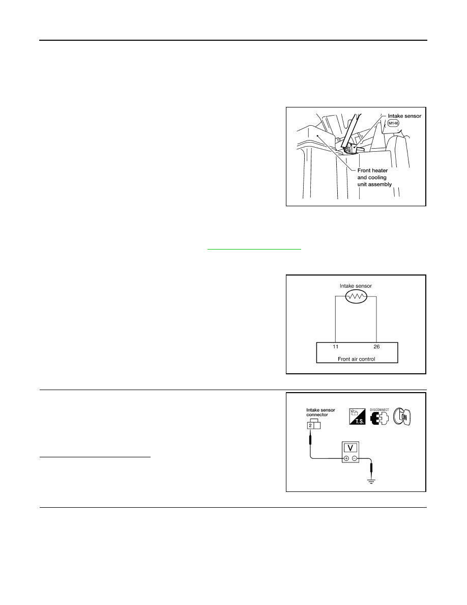
Intake Sensor
The intake sensor is located on top of the heater and cooling unit
assembly next to the A/C evaporator cover. It converts temperature
of air after it passes through the evaporator into a resistance value
which is then input to the front air control.
Intake Sensor Diagnosis Procedure
INFOID:0000000009482485
Regarding Wiring Diagram information, refer to
DIAGNOSTIC PROCEDURE FOR INTAKE SENSOR
SYMPTOM: Intake sensor circuit is open or shorted.
1.
CHECK VOLTAGE BETWEEN INTAKE SENSOR AND GROUND
1. Disconnect intake sensor connector.
2. Turn ignition switch ON.
3. Check voltage between intake sensor harness connector M146
terminal 2 and ground.
Is the inspection result normal?
YES
>> GO TO 2.
NO
>> GO TO 4.
2.
CHECK CIRCUIT CONTINUITY BETWEEN INTAKE SENSOR AND FRONT AIR CONTROL
WJIA1155E
AWIIA0433GB
2 - Ground
: Approx. 5V
WJIA1278E