Nissan Xterra. Manual - part 441
FSU-20
< UNIT REMOVAL AND INSTALLATION >
KNUCKLE
KNUCKLE
Removal and Installation
INFOID:0000000009484392
REMOVAL
1. Remove wheel and tire from vehicle using power tool. Refer to
2. Remove the engine under cover (if equipped). Refer to
EXT-15, "Removal and Installation"
3. Without disassembling the hydraulic lines, remove brake caliper using power tool. Reposition it aside with
wire. Refer to
BR-34, "Removal and Installation of Brake Caliper and Disc Rotor"
CAUTION:
Do not press brake pedal while caliper is removed.
4. Put alignment marks on disc rotor and wheel hub and bearing
assembly, then remove disc rotor.
5. Disconnect wheel sensor and remove bracket from steering knuckle.
CAUTION:
Do not pull on wheel sensor harness.
6. On 4WD models, remove cotter pin, then remove lock nut from drive shaft using power tool. Refer to
.
CAUTION:
Do not reuse cotter pin.
7. Remove steering outer socket cotter pin at steering knuckle, then loosen nut using power tool. Refer to
ST-15, "Removal and Installation"
.
CAUTION:
Do not reuse cotter pin.
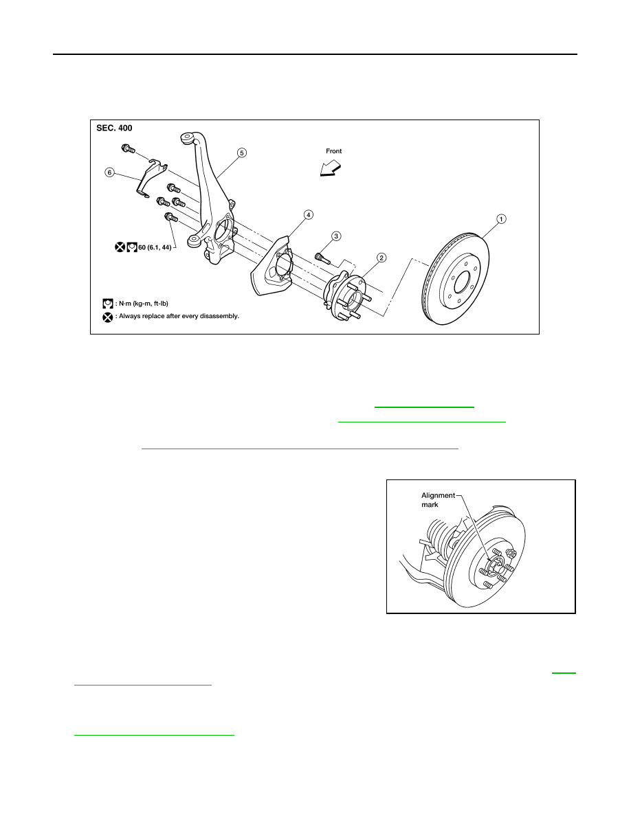
1.
Disc rotor
2.
Wheel hub and bearing assembly
3.
Wheel stud
4.
Splash guard
5.
Steering knuckle
6.
Wheel sensor bracket
WDIA0228E
WDIA0044E