Nissan Xterra. Manual - part 361


  Index      Nissan     Nissan Xterra (2014 year) - Service and Repair Manual


Search            


Content   ..  359  360  361  362   ..


Nissan Xterra. Manual - part 361


EM-72

< REMOVAL AND INSTALLATION >

[VQ40DE]

REAR TIMING CHAIN CASE

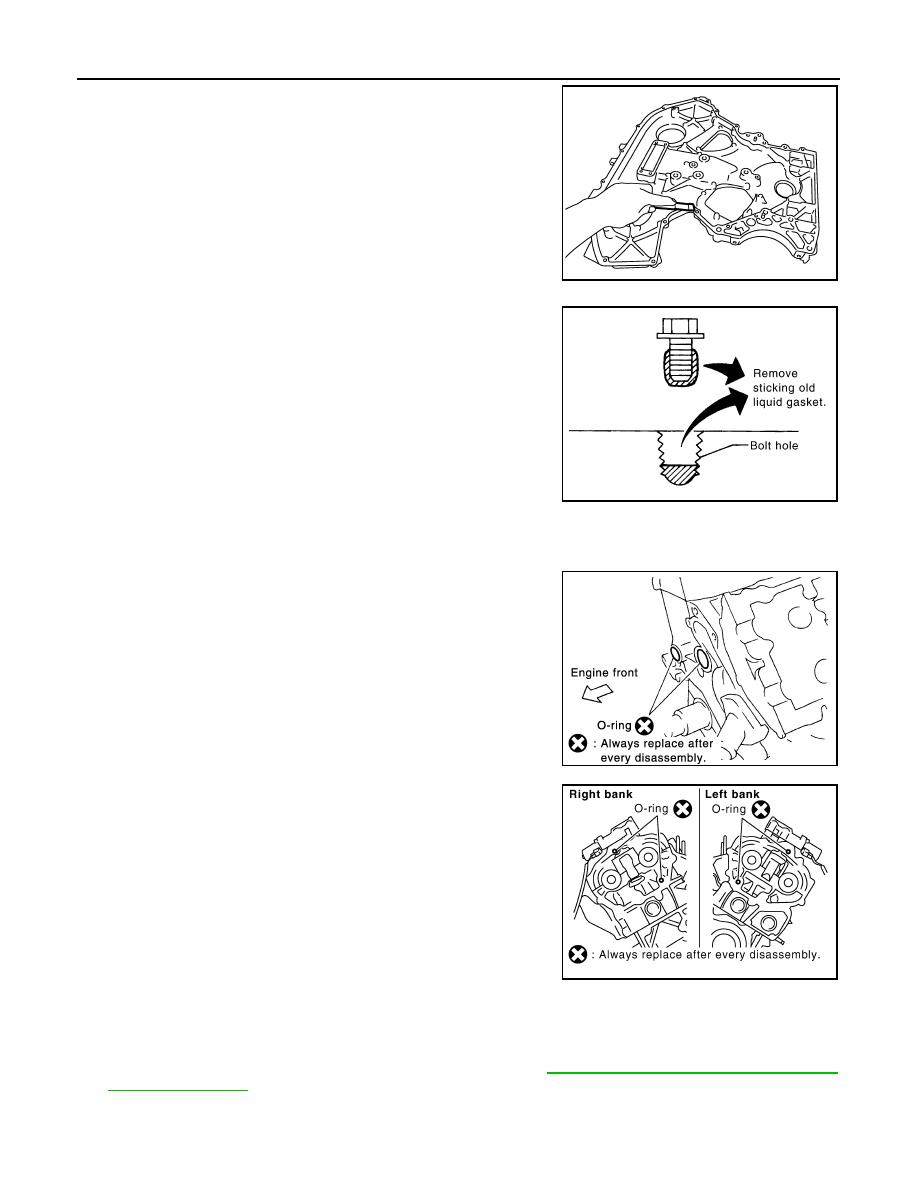
8. Use scraper to remove all traces of old liquid gasket from rear

timing chain case, and opposite mating surfaces.

• Remove old liquid gasket from bolt hole and thread.

INSTALLATION

1. Install rear timing chain case as follows:
a. Install new O-rings onto cylinder block.

CAUTION:

Do not reuse O-rings.

b. Install new O-rings to cylinder head and camshaft bracket

(No. 1).

CAUTION:

Do not reuse O-rings.

c.

Apply liquid gasket using Tool to rear timing chain case back side as shown.

Use Genuine RTV Silicone Sealant or equivalent. Refer to 

GI-21, "Recommended Chemical Prod-

ucts and Sealants"

.

CAUTION:

• For “A”, completely wipe off liquid gasket covering the area shown.

PBIC2910E

PBIC2084E

PBIC0788E

SBIA0496E

Tool number

: WS39930000 (

)

REAR TIMING CHAIN CASE

EM-73

< REMOVAL AND INSTALLATION >

[VQ40DE]

C

D

E

F

G

H

I

J

K

L

M

A

EM

N

P

O

• Apply liquid gasket on installation position of water pump and cylinder head very completely.

d. Align rear timing chain case with dowel pins (right and left) on cylinder block and install rear timing chain

case.

• Make sure O-rings stay in place during installation to cylinder block, cylinder head and camshaft bracket

(No. 1).

CAUTION:

Do not reuse O-rings.

e. Tighten bolts in numerical order as shown.

• There are two type of bolts with different torque specifications.

Refer to the following for installing bolts. 

f.

After all bolts are tightened, retighten them to the specified torque in numerical order as shown.

• If liquid gasket protrudes, wipe it off immediately.

Bolt length Bolt position

Torque specification

20 mm 
(0.79 in)

1, 2, 3, 6, 7, 8, 
9, 10

: 12.7 N·m (1.3 kg-m, 9 ft-lb)

16 mm 
(0.63 in)

4, 5, 11

: 12.7 N·m (1.3 kg-m, 9 ft-lb)

16 mm 
(0.63 in)

12 through 26 : 15.0 N·m (1.5 kg-m, 11 ft-lb)

PBIC2924E

PBIC2921E

EM-74

< REMOVAL AND INSTALLATION >

[VQ40DE]

REAR TIMING CHAIN CASE

g. After installing rear timing chain case, check the surface height

difference between following parts on oil pan (upper) mounting

surface.

• If not within the standard, repeat the installation procedure.

2. Install water pump with new O-rings, if removed. Refer to 

CO-21, "Removal and Installation"

.

CAUTION:

Do not reuse O-rings.

3. Install timing chains and related components. Refer to 

EM-59, "Removal and Installation"

 and 

EM-68,

"Removal and Installation (Secondary Timing Chain Tensioner)"

.

4. Install front timing chain case. Refer to 

EM-51, "Removal and Installation"

.

5. Install oil pan (upper) and (lower). Refer to 

EM-34, "Removal and Installation"

.

INSPECTION AFTER INSTALLATION

• Before starting engine, check oil/fluid levels including engine coolant and engine oil. If less than required

quantity, fill to the specified level. Refer to 

MA-12, "Fluids and Lubricants"

.

• Use procedure below to check for fuel leakage.

• Turn ignition switch ON (with engine stopped). With fuel pressure applied to fuel piping, check for fuel leak-

age at connection points.

• Start engine. With engine speed increased, check again for fuel leakage at connection points.

• Run engine to check for unusual noise and vibration.

NOTE:

If hydraulic pressure inside timing chain tensioner drops after removal and installation, slack in the guide

may generate a pounding noise during and just after engine start. However, this is normal. Noise will stop

after hydraulic pressure rises.

• Warm up engine thoroughly to make sure there is no leakage of fuel, exhaust gas, or any oils/fluids including

engine oil and engine coolant.

• Bleed air from passages in lines and hoses, such as in cooling system.

• After cooling down engine, again check oil/fluid levels including engine oil and engine coolant. Refill to spec-

ified level, if necessary.

• Summary of the inspection items:

*Power steering fluid, brake fluid, etc.

Standard

Rear timing chain case to lower cylinder block:

–0.24 to 0.14 mm (–0.0094 to 0.0055 in)

PBIC2925E

Item

Before starting engine

Engine running

After engine stopped

Engine coolant

Level

Leakage

Level

Engine oil

Level

Leakage

Level

Transmission/
transaxle fluid 

A/T and CVT Models

Leakage

Level/Leakage

Leakage

M/T Models

Level/Leakage

Leakage

Level/Leakage

Other oils and fluids*

Level

Leakage

Level

Fuel

Leakage

Leakage

Leakage

Exhaust gas

Leakage

CAMSHAFT

EM-75

< REMOVAL AND INSTALLATION >

[VQ40DE]

C

D

E

F

G

H

I

J

K

L

M

A

EM

N

P

O

CAMSHAFT

Exploded View

INFOID:0000000009484479

1.

Intake valve timing control solenoid 
valve (RH bank)

2.

Gasket

3.

Camshaft bracket (No. 2 to 4)

4.

Camshaft (EXH)

5.

Camshaft (INT)

6.

Camshaft bracket (No. 1)

7.

Dowel pin

8.

Valve lifter

9.

O-ring

10.

Timing chain tensioner (secondary) 
(RH bank)

11. Spring

12. Plunger

13.

Timing chain tensioner (secondary) 
(LH bank)

14. Cylinder head (RH bank)

15. Cylinder head (LH bank)

16. O-ring

17.

Camshaft position sensor (PHASE) 
(RH bank)

18.

Camshaft position sensor (PHASE) 
(LH bank)

19. Intake valve timing control solenoid 

valve (LH bank)

PBIC2930E


Content   ..  359  360  361  362   ..