Nissan Xterra. Manual - part 339
EC-482
< DTC/CIRCUIT DIAGNOSIS >
[VQ40DE]
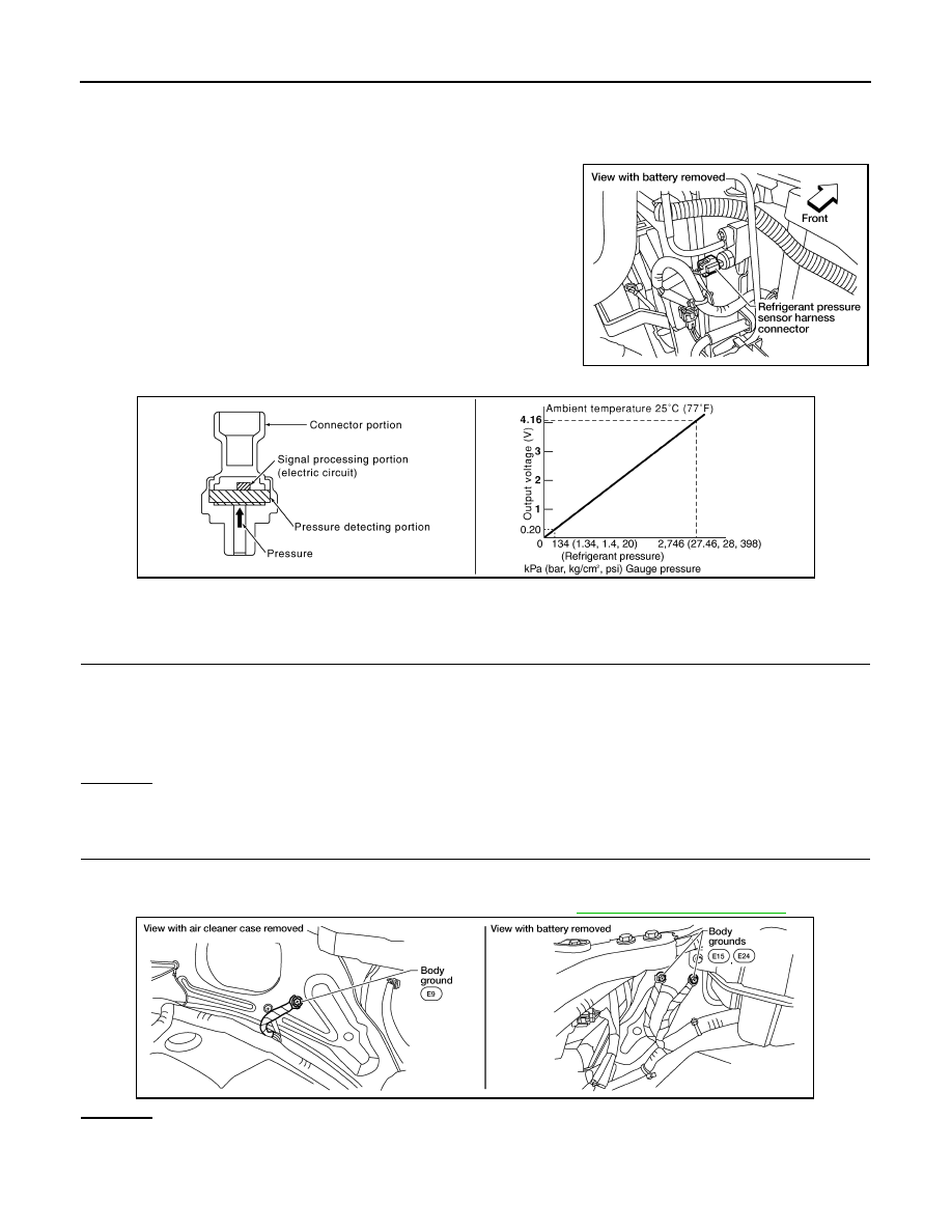
REFRIGERANT PRESSURE SENSOR
REFRIGERANT PRESSURE SENSOR
Component Description
INFOID:0000000009484233
The refrigerant pressure sensor is installed at the condenser of the
air conditioner system. The sensor uses an electrostatic volume
pressure transducer to convert refrigerant pressure to voltage. The
voltage signal is sent to ECM, and ECM controls cooling fan system.
Diagnosis Procedure
INFOID:0000000009484234
1.
CHECK REFRIGERANT PRESSURE SENSOR OVERALL FUNCTION
1. Start engine and warm it up to normal operating temperature.
2. Turn A/C switch and blower switch ON.
3. Check voltage between ECM terminal 63 and ground with CONSULT or tester.
OK or NG
OK
>> INSPECTION END
NG
>> GO TO 2.
2.
CHECK GROUND CONNECTIONS
1. Turn A/C switch and blower switch OFF.
2. Turn ignition switch OFF.
3. Loosen and retighten three ground screws on the body. Refer to
OK or NG
OK
>> GO TO 3.
NG
>> Repair or replace ground connections.
BBIA0564E
PBIB2657E
Voltage: 1.0 - 4.0V
BBIA0539E