Nissan Xterra. Manual - part 333
EC-458
< DTC/CIRCUIT DIAGNOSIS >
[VQ40DE]
ASCD INDICATOR
ASCD INDICATOR
Component Description
INFOID:0000000009484212
ASCD indicator lamp illuminates to indicate ASCD operation status. Lamp has two indicators, CRUISE and
SET, and is integrated in combination meter.
CRUISE indicator illuminates when MAIN switch on ASCD steering switch is turned ON to indicated that
ASCD system is ready for operation.
SET indicator illuminates when the following conditions are met.
• CRUISE indicator is illuminated.
• SET/COAST switch on ASCD steering switch is turned ON while vehicle speed is within the range of the
ASCD setting.
SET indicator remains lit during ASCD control.
for the ASCD function.
Diagnosis Procedure
INFOID:0000000009484213
1.
CHECK OVERALL FUNCTION
Check ASCD indicator under the following conditions.
OK or NG
OK
>> INSPECTION END
NG
>> GO TO 2.
2.
CHECK DTC
Check that DTC UXXXX is not displayed.
OK or NG
OK
>> GO TO 3.
NG
>> Perform trouble diagnoses for DTC UXXXX.
3.
CHECK COMBINATION METER FUNCTION
.
OK or NG
OK
>> GO TO 4.
NG
>> Go to
MWI-5, "METER SYSTEM : System Diagram"
.
4.
CHECK INTERMITTENT INCIDENT
GI-40, "Intermittent Incident"
>> INSPECTION END
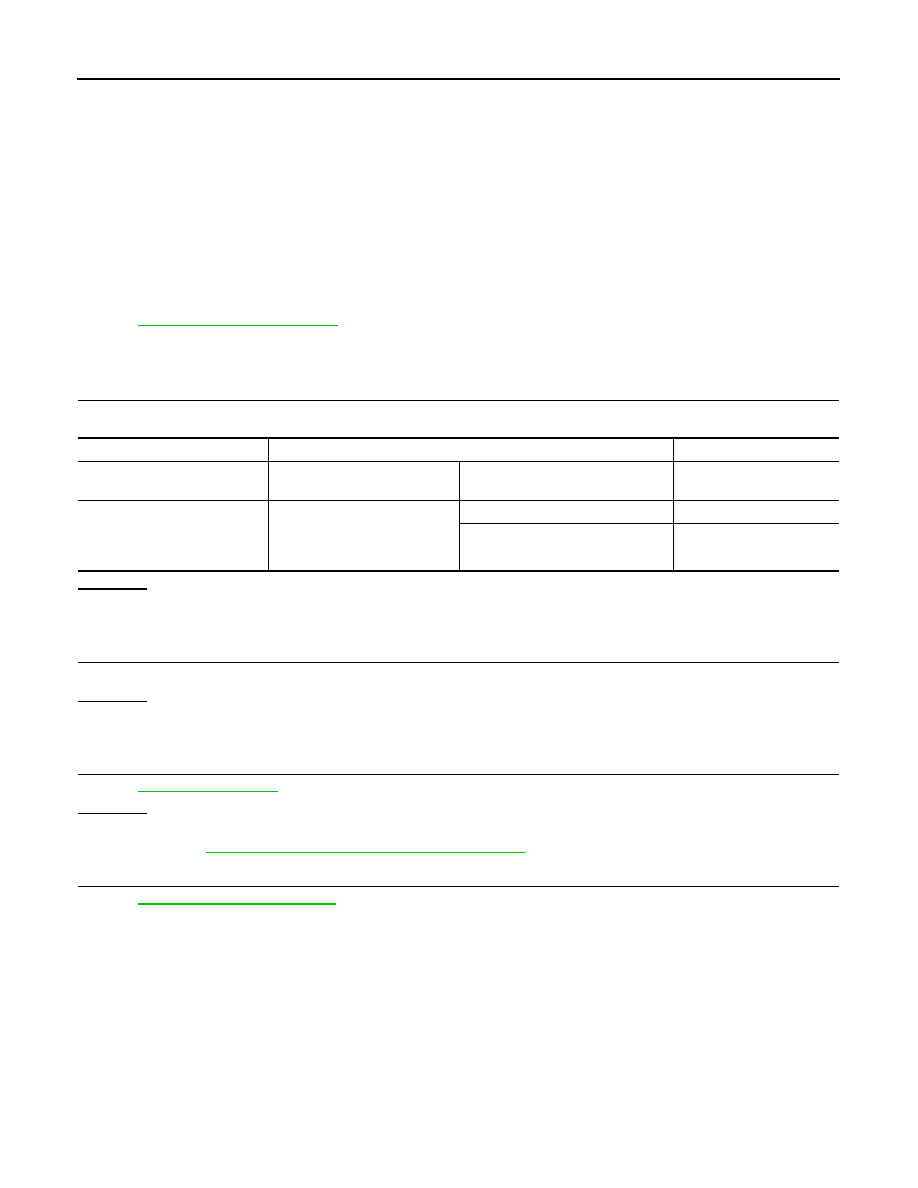
ASCD INDICATOR
CONDITION
SPECIFICATION
CRUISE LAMP
• Ignition switch: ON
MAIN switch: pressed at the 1st time
→ at the 2nd time
ON
→ OFF
SET LAMP
• MAIN switch: ON
• When vehicle speed is be-
tween 40 km/h (25 MPH) and
144 km/h (89 MPH)
ASCD: Operating
ON
ASCD: Not operating
OFF