Nissan Xterra. Manual - part 269
EC-202
< DTC/CIRCUIT DIAGNOSIS >
[VQ40DE]
P0130, P0150 A/F SENSOR 1
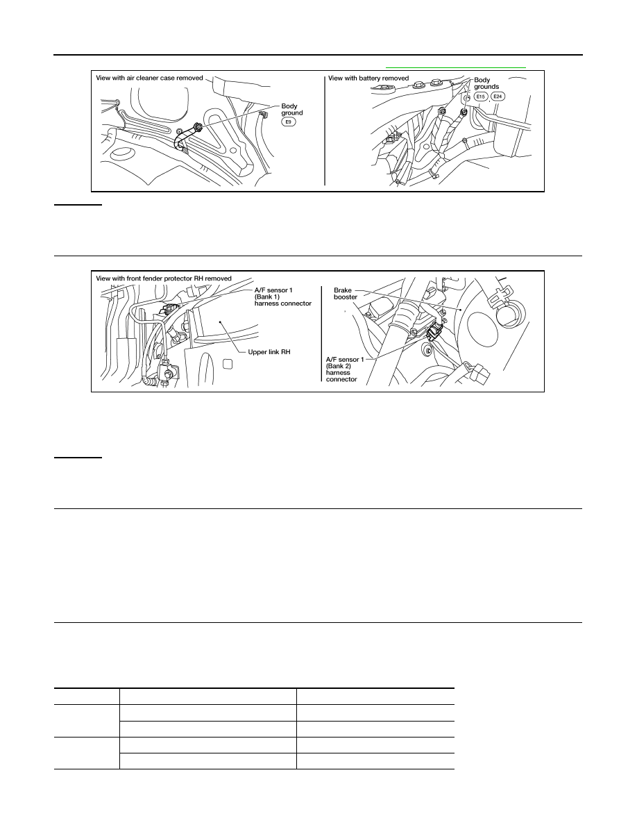
2. Loosen and retighten three ground screws on the body. Refer to
OK or NG
OK
>> GO TO 2.
NG
>> Repair or replace ground connections.
2.
CHECK AIR FUEL RATIO (A/F) SENSOR 1 POWER SUPPLY CIRCUIT
1. Disconnect A/F sensor 1 harness connector.
2. Turn ignition switch ON.
3. Check voltage between A/F sensor 1 terminal 4 and ground with CONSULT or tester.
OK or NG
OK
>> GO TO 4.
NG
>> GO TO 3.
3.
DETECT MALFUNCTIONING PART
Check the following.
• Harness connectors E2, F32
• IPDM E/R harness connector E119
• 15A fuse (No. 54)
• Harness for open or short between A/F sensor 1 and fuse
>> Repair or replace harness or connectors.
4.
CHECK A/F SENSOR 1 INPUT SIGNAL CIRCUIT FOR OPEN AND SHORT
1. Turn ignition switch OFF.
2. Disconnect ECM harness connector.
3. Check harness continuity between A/F sensor 1 terminal and ECM terminal as follows.
Refer to Wiring Diagram.
BBIA0539E
Voltage: Battery voltage
BBIA0544E
A/F sensor 1 terminal
ECM terminal
Bank1
1
69
2
73
Bank 2
1
77
2
81