Nissan Xterra. Manual - part 259


  Index      Nissan     Nissan Xterra (2014 year) - Service and Repair Manual


Search            


Content   ..  257  258  259  260   ..


Nissan Xterra. Manual - part 259


EC-162

< DTC/CIRCUIT DIAGNOSIS >

[VQ40DE]

P0037, P0038, P0057, P0058 HO2S2 HEATER

4. Turn ignition switch ON.
5. Turn ignition switch OFF and wait at least 10 seconds.
6. Start the engine and keep the engine speed between 3,500 rpm and 4,000 rpm for at least 1 minute under

no load.

7. Let engine idle for 1 minute.
8. Check 1st trip DTC.
9. If 1st trip DTC is detected, go to 

EC-162, "Diagnosis Procedure"

.

 WITH GST

Follow the procedure “WITH CONSULT” above.

Diagnosis Procedure

INFOID:0000000009483846

1.

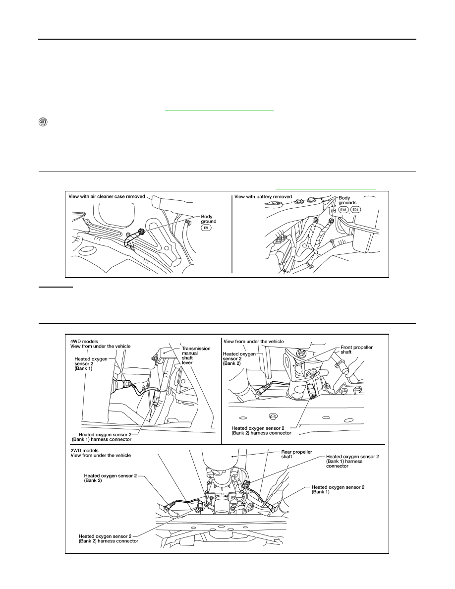
CHECK GROUND CONNECTIONS

1. Turn ignition switch OFF.

2. Loosen and retighten three ground screws on the body. Refer to 

EC-152, "Ground Inspection"

.

OK or NG

OK

>> GO TO 2.

NG

>> Repair or replace ground connections.

2.

CHECK HO2S2 POWER SUPPLY CIRCUIT

1. Disconnect heated oxygen sensor 2 harness connector.

2. Turn ignition switch ON.

BBIA0539E

BBIA0540E

P0037, P0038, P0057, P0058 HO2S2 HEATER

EC-163

< DTC/CIRCUIT DIAGNOSIS >

[VQ40DE]

C

D

E

F

G

H

I

J

K

L

M

A

EC

N

P

O

3. Check voltage between HO2S2 terminal 3 and ground with CONSULT or tester.

OK or NG

OK

>> GO TO 4.

NG

>> GO TO 3.

3.

DETECT MALFUNCTIONING PART

Check the following.

• Harness connectors E2, F32

• IPDM E/R harness connector E119

• 15 A fuse (No.54)

• Harness for open or short between heated oxygen sensor 2 and fuse

>> Repair harness or connectors.

4.

CHECK HO2S2 OUTPUT SIGNAL CIRCUIT FOR OPEN AND SHORT

1. Turn ignition switch OFF.

2. Disconnect ECM harness connector.

3. Check harness continuity between ECM terminal and HO2S2 terminal as follows.

Refer to Wiring Diagram.

4. Also check harness for short to ground and short to power.
OK or NG

OK

>> GO TO 5.

NG

>> Repair open circuit or short to ground or short to power in harness or connectors.

5.

CHECK HEATED OXYGEN SENSOR 2 HEATER

Refer to 

EC-163, "Component Inspection"

.

OK or NG

OK

>> GO TO 6.

NG

>> Replace malfunctioning heated oxygen sensor 2. Refer to 

EX-5, "Exploded View"

.

6.

CHECK INTERMITTENT INCIDENT

Refer to 

GI-40, "Intermittent Incident"

.

>> INSPECTION END

Component Inspection

INFOID:0000000009483847

HEATED OXYGEN SENSOR 2 HEATER

1. Check resistance between HO2S2 terminals as follows.

2. If NG, replace heated oxygen sensor 2. Refer to 

EX-5, "Exploded View"

.

Voltage: Battery voltage

DTC

Terminals

Bank

ECM

Sensor

P0037, P0038

37

2

1

P0057, P0058

41

2

2

Continuity should exist.

Terminal No.

Resistance

2 and 3

3.4 - 4.4 

Ω [at 25°C (77°F)]

1 and 2, 3, 4

∞ Ω

(Continuity should not exist)

4 and 1, 2, 3

EC-164

< DTC/CIRCUIT DIAGNOSIS >

[VQ40DE]

P0037, P0038, P0057, P0058 HO2S2 HEATER

CAUTION:

• Discard any heated oxygen sensor which has been dropped from a height of more than 0.5 m (19.7

in) onto a hard surface such as a concrete floor; use a new one.

• Before installing new oxygen sensor, clean exhaust system threads using Oxygen Sensor Thread

Cleaner tool J-43897-18 or J-43897-12 and approved anti-seize lubricant.

P0075, P0081 IVT CONTROL SOLENOID VALVE

EC-165

< DTC/CIRCUIT DIAGNOSIS >

[VQ40DE]

C

D

E

F

G

H

I

J

K

L

M

A

EC

N

P

O

P0075, P0081 IVT CONTROL SOLENOID VALVE

Component Description

INFOID:0000000009483848

Intake valve timing control solenoid valve is activated by ON/OFF

pulse duty (ratio) signals from the ECM.

The intake valve timing control solenoid valve changes the oil

amount and direction of flow through intake valve timing control unit

or stops oil flow.

The longer pulse width advances valve angle.

The shorter pulse width retards valve angle.

When ON and OFF pulse widths become equal, the solenoid valve

stops oil pressure flow to fix the intake valve angle at the control

position.

On Board Diagnosis Logic

INFOID:0000000009483849

DTC Confirmation Procedure

INFOID:0000000009483850

1. If DTC Confirmation Procedure has been previously conducted, always perform the following before con-

ducting the next step.

a. Turn ignition switch OFF and wait at least 10 seconds.
b. Turn ignition switch ON.
c. Turn ignition switch OFF and wait at least 10 seconds.
2. Start engine and let it idle for 5 seconds.
3. Check 1st trip DTC.
4. If 1st trip DTC is detected, go to 

EC-165, "Diagnosis Procedure"

.

Diagnosis Procedure

INFOID:0000000009483851

1.

CHECK INTAKE VALVE TIMING CONTROL SOLENOID VALVE POWER SUPPLY CIRCUIT

1. Turn ignition switch OFF.

2. Disconnect intake valve timing control solenoid valve harness connector.

PBIB1842E

DTC No.

Trouble diagnosis name

DTC detecting condition

Possible cause

P0075
0075
(Bank 1)

Intake valve timing control 
solenoid valve circuit

An improper voltage is sent to the ECM 
through intake valve timing control solenoid 
valve.

• Harness or connectors

(Intake valve timing control solenoid valve 
circuit is open or shorted.)

• Intake valve timing control solenoid valve

P0081
0081
(Bank 2)

1.

Intake manifold collector

2.

Intake valve timing control solenoid 
valve (Bank 1)

3.

Intake valve timing control solenoid 
valve (Bank 2)

: Front

AWBIA0685ZZ


Content   ..  257  258  259  260   ..