Nissan Xterra. Manual - part 178


  Index      Nissan     Nissan Xterra (2014 year) - Service and Repair Manual


Search            


Content   ..  176  177  178  179   ..


Nissan Xterra. Manual - part 178


WATER INLET AND THERMOSTAT ASSEMBLY

CO-27

< REMOVAL AND INSTALLATION >

[VQ40DE]

C

D

E

F

G

H

I

J

K

L

M

A

CO

N

P

O

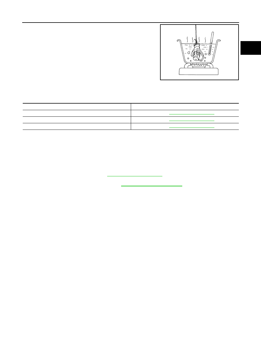
2. Check valve operation.

• Place a thread so that it is caught in the valve of the thermo-

stat. Immerse fully in a container filled with water. Heat while

stirring.

• The valve opening temperature is the temperature at which

the valve opens and falls from the thread.

• Continue heating. Check the full-open lift amount.

NOTE:

The full-open lift amount standard temperature is the reference

value.

• After checking the full-open lift amount, lower the water temperature and check the valve closing tem-

perature.

• If valve seating at measured values are out of standard range, replace water inlet and thermostat

assembly.

INSTALLATION

Installation is in the reverse order of removal.

CAUTION:

Do not spill engine coolant in engine room. Use a shop cloth to absorb engine coolant.

INSPECTION AFTER INSTALLATION

• Check for engine coolant leaks. Refer to 

CO-10, "System Inspection"

.

• Start and warm up engine. Visually check for coolant leaks. Repair as necessary.

• Check and adjust engine coolant level. Refer to 

MA-12, "Fluids and Lubricants"

SLC949A

Thermostat

Standard

Valve opening temperature

Refer to 

CO-30, "Standard and Limit"

.

Full-open lift amount

Refer to 

CO-30, "Standard and Limit"

.

Valve closing temperature

Refer to 

CO-30, "Standard and Limit"

.

CO-28

< REMOVAL AND INSTALLATION >

[VQ40DE]

WATER OUTLET AND WATER PIPING

WATER OUTLET AND WATER PIPING

Exploded View

INFOID:0000000009484592

Removal and Installation

INFOID:0000000009484593

WARNING:

Do not remove the radiator cap when the engine is hot. Serious burns could occur from high pressure

engine coolant escaping from the radiator. Wrap a thick cloth around the cap. Slowly turn it a quarter

of a turn to release built-up pressure. Carefully remove radiator cap by turning it all the way.

NOTE:

When removing components such as hoses, tubes/lines, etc., cap or plug openings to prevent fluid from spill-

ing.

REMOVAL

1. Drain engine coolant from radiator. Refer to 

CO-11, "Changing Engine Coolant"

.

CAUTION:

• Perform this step when engine is cold.

• Do not spill engine coolant on drive belts.

2. Remove the intake manifold collector. Refer to 

EM-25, "Removal and Installation"

.

3. Remove engine coolant temperature sensor as necessary.

CAUTION:

Be careful not to damage engine coolant temperature sensor.

4. Remove water outlet and gaskets, heater pipe, water bypass hoses and water pipe.

1.

Engine coolant temperature sensor

2.

Washer

3.

Water outlet

4.

Heater hose

5.

O-ring

6.

Water pipe

7.

Water hose

8.

Radiator hose (upper)

9.

Water hose

10. Water hose

11. Gasket

12. Heater pipe

13. Heater hose

14. Gasket

A.

From electric throttle control actuator

B.

To electric throttle control actuator

C.

To heater

D.

From heater

AWBIA1025GB

WATER OUTLET AND WATER PIPING

CO-29

< REMOVAL AND INSTALLATION >

[VQ40DE]

C

D

E

F

G

H

I

J

K

L

M

A

CO

N

P

O

CAUTION:

Do not reuse gaskets.

INSTALLATION

Installation is in the reverse order of removal, paying attention to the following.

• Securely insert each hose, and install clamp at a position where it does not interfere with the pipe bulge.

• When inserting water pipe into water outlet, apply mild soap to O-ring.

CAUTION:

Do not reuse O-ring.

INSPECTION AFTER INSTALLATION

• Check for engine coolant leaks. Refer to 

CO-10, "System Inspection"

.

• Start and warm up engine. Visually check for coolant leaks. Repair as necessary.

• Check and adjust engine coolant level. Refer to 

MA-12, "Fluids and Lubricants"

CO-30

< SERVICE DATA AND SPECIFICATIONS (SDS) 

[VQ40DE]

SERVICE DATA AND SPECIFICATIONS (SDS)

SERVICE DATA AND SPECIFICATIONS (SDS)

SERVICE DATA AND SPECIFICATIONS (SDS)

Standard and Limit

INFOID:0000000009484594

ENGINE COOLANT CAPACITY (APPROXIMATE)

Unit:   (US qt, Imp qt)

RADIATOR

Unit: kPa (kg/cm

2

, psi)

THERMOSTAT

Engine coolant capacity (With reservoir tank at “MAX” level)

10.2 (10-3/4, 9)

Reservoir cap relief pressure

Standard

98 - 118 (1.0 - 1.2, 14 - 17)

Testing pressure

157 (1.6, 23)

Valve opening temperature

80.5 - 83.5

°C (177 - 182°F)

Full-open lift amount

8.6 mm / 95

°C (0.339 in / 203°F)

Valve closing temperature

77

°C (171°F)


Content   ..  176  177  178  179   ..