Nissan Xterra. Manual - part 163


  Index      Nissan     Nissan Xterra (2014 year) - Service and Repair Manual


Search            


Content   ..  161  162  163  164   ..


Nissan Xterra. Manual - part 163


CHG

L TERMINAL CIRCUIT (OPEN)

CHG-15

< DTC/CIRCUIT DIAGNOSIS >

C

D

E

F

G

H

I

J

K

L

B

A

O

P

N

Is the inspection result normal?

YES

>> GO TO 5.

NO

>> Repair or replace the harness or connectors.

5.

CHECK POWER SUPPLY CIRCUIT 

1. Connect the battery cable to the negative terminal.

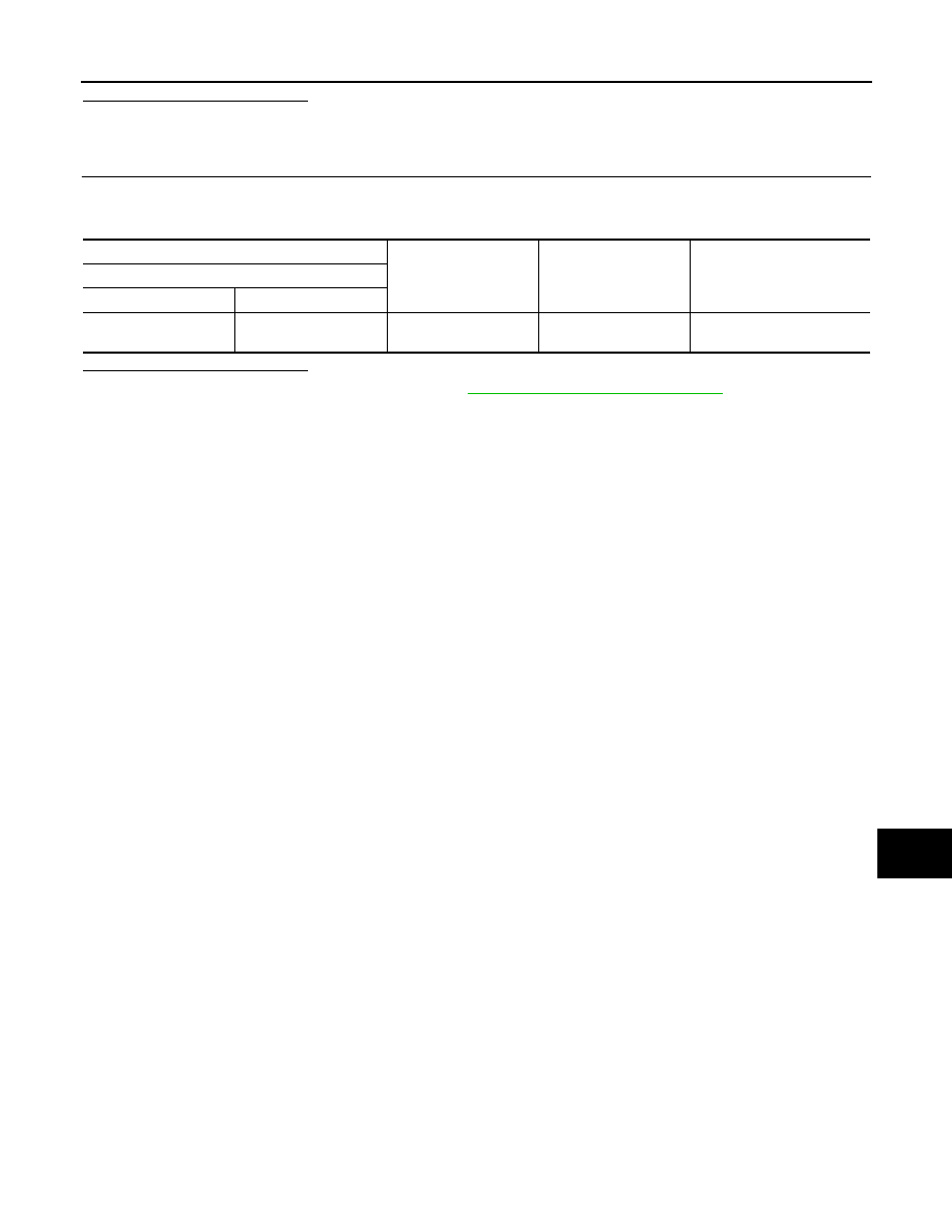
2. Check voltage between combination meter harness connector and ground.

Is the inspection result normal?

YES

>> Replace the combination meter. Refer to 

MWI-84, "Removal and Installation"

.

NO

>> Repair or replace the harness or connectors. 

(+)

(-)

Condition 

Voltage 

(Approx.)

Combination meter 

Connector

Terminal

M24

16

Ground

When the ignition 

switch is in ON position

Battery voltage

CHG-16

< DTC/CIRCUIT DIAGNOSIS >

L TERMINAL CIRCUIT (SHORT)

L TERMINAL CIRCUIT (SHORT)

Description

INFOID:0000000009484987

The terminal “2” (L) circuit controls the charge warning lamp. The charge warning lamp illuminates when the

ignition switch is set to ON or START. When the generator is providing sufficient voltage with the engine run-

ning, the charge warning lamp will go off. If the charge warning lamp illuminates with the engine running, a

malfunction is indicated.

Diagnosis Procedure

INFOID:0000000009484988

Regarding Wiring Diagram information, refer to 

CHG-18, "Wiring Diagram"

.

1.

CHECK “L” TERMINAL CIRCUIT (SHORT)

1. Turn ignition switch OFF. 

2. Disconnect generator connector.

3. Turn ignition switch ON.
Does charge warning lamp illuminate?

YES

>> GO TO 2.

NO

>> Refer to 

CHG-2, "Work Flow (With EXP-800 NI or GR8-1200 NI)"

 or 

CHG-5, "Work Flow (Without

EXP-800 NI or GR8-1200 NI)"

2.

CHECK HARNESS CONTINUITY (SHORT CIRCUIT)

1. Turn ignition switch OFF.

2. Disconnect the battery cable from the negative terminal. 

3. Disconnect combination meter connector.

4. Check continuity between the combination meter harness connector and ground.

Is the inspection result normal?

YES

>> Replace the combination meter. Refer to 

MWI-84, "Removal and Installation"

NO

>> Repair or replace the harness or connectors. 

Combination meter

Ground

Continuity

Connector

Terminal

M24

2

No

CHG

S TERMINAL CIRCUIT

CHG-17

< DTC/CIRCUIT DIAGNOSIS >

C

D

E

F

G

H

I

J

K

L

B

A

O

P

N

S TERMINAL CIRCUIT

Description

INFOID:0000000009484989

The output voltage of the generator is controlled by the IC regulator at terminal “3” (S) detecting the input volt-

age. Terminal “3” circuit detects the battery voltage to adjust the generator output voltage with the IC regulator.

Diagnosis Procedure

INFOID:0000000009484990

Regarding Wiring Diagram information, refer to 

CHG-18, "Wiring Diagram"

.

1.

CHECK “S” TERMINAL CONNECTION

1. Turn ignition switch OFF.

2. Check if “S” terminal is clean and tight.

 
Is the inspection result normal?

YES

>> GO TO 2.

NO

>> Repair “S” terminal connection. Confirm repair by performing complete Charging system test

using EXP-800 NI or GR8-1200 NI (if available). Refer to applicable Instruction Manual for proper

testing procedures.

2.

CHECK VOLTAGE REGULATOR CIRCUIT

Check voltage between generator harness connector E205 terminal

3 and ground.

Does battery voltage exist?

YES

>> Refer to 

CHG-2, "Work Flow (With EXP-800 NI or GR8-

1200 NI)"

 or 

CHG-5, "Work Flow (Without EXP-800 NI

or GR8-1200 NI)"

.

NO

>> Check harness for open between generator and fuse.

(+)

(-)

Voltage (approx.)

Connector

Terminal

E205

3

Ground

Battery voltage

AWMIA0711ZZ

CHG-18

< WIRING DIAGRAM >

CHARGING SYSTEM

WIRING DIAGRAM

CHARGING SYSTEM

Wiring Diagram

INFOID:0000000009484991

ABMWA2354GB


Content   ..  161  162  163  164   ..