Nissan Xterra. Manual - part 123
DIAGNOSIS SYSTEM [ABS ACTUATOR AND ELECTRIC UNIT (CONTROL
UNIT)]
BRC-149
< SYSTEM DESCRIPTION >
[TYPE 2]
C
D
E
G
H
I
J
K
L
M
A
B
BRC
N
O
P
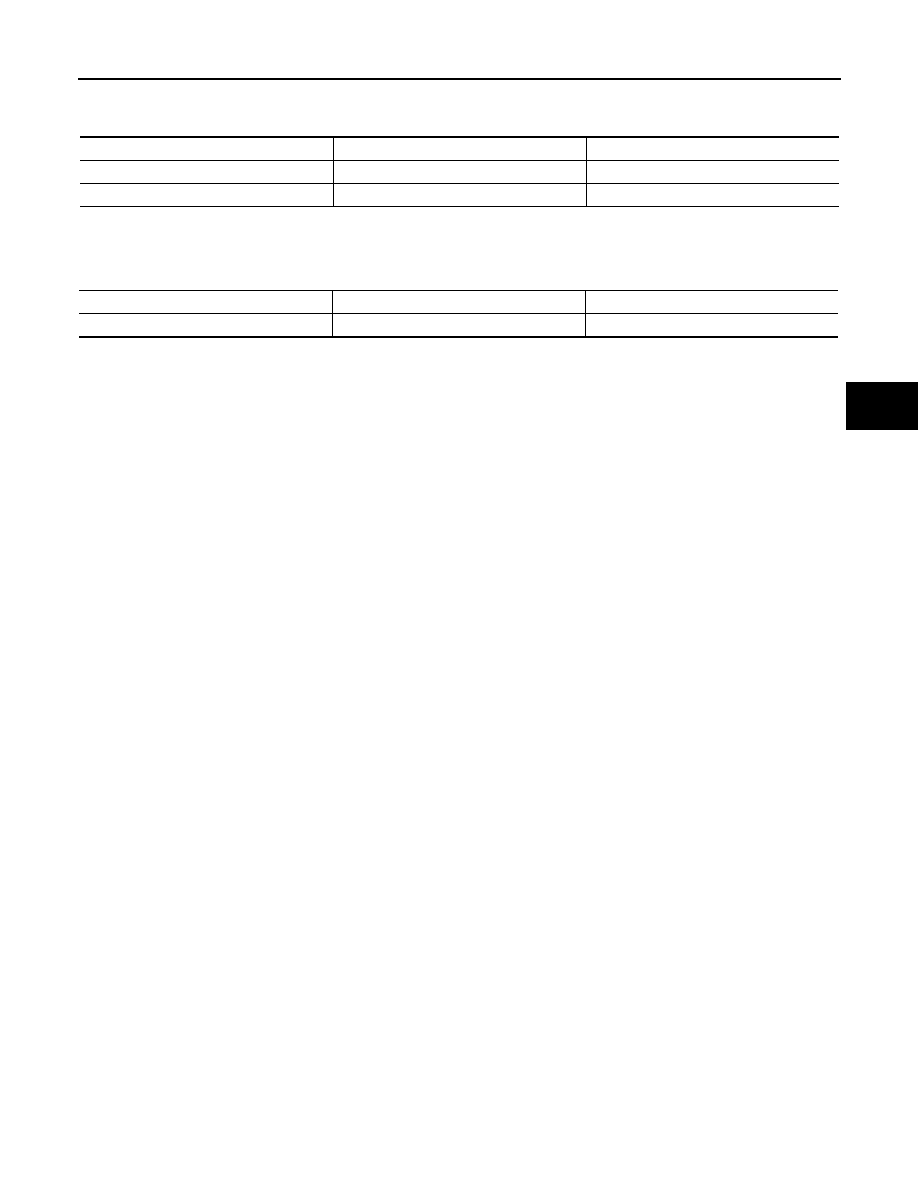
ABS MOTOR
• Touch “On” and “Off” on screen. Make sure motor relay and actuator relay operate as shown in table below.
STOP LAMP ON RELAY
• Touch “On” and “Off” on screen. Make sure stop lamp relay operates as shown in table below. Brake lamps
will illuminate when relay is “On”.
Operation
On
Off
MOTOR RELAY
On
Off
ACTUATOR RLY
On
On
Operation
On
Off
STP ON RLY
On
Off