Nissan Xterra. Manual - part 104
C1164, C1165, C1166, C1167 CV/SV SYSTEM
BRC-73
< DTC/CIRCUIT DIAGNOSIS >
[TYPE 1]
C
D
E
G
H
I
J
K
L
M
A
B
BRC
N
O
P
YES
>> GO TO 2
NO
>> Poor connection of connector terminals. Repair or replace connector.
2.
CHECK SOLENOID, VDC SWITCH-OVER VALVE AND ACTUATOR RELAY POWER SUPPLY CIRCUIT
1. Turn ignition switch OFF.
2. Disconnect ABS actuator and electric unit (control unit) connector.
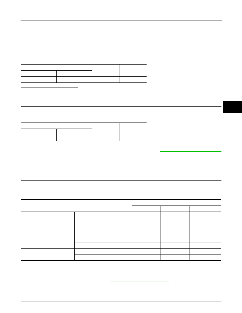
3. Check voltage between ABS actuator and electric unit (control unit) connector E125 terminal 32 and
ground.
Is the inspection result normal?
YES
>> GO TO 3
NO
>> Repair or replace malfunctioning components.
3.
CHECK SOLENOID, VDC SWITCH-OVER VALVE AND ACTUATOR RELAY GROUND CIRCUIT
Check continuity between ABS actuator and electric unit (control unit) connector E125 terminals 16, 47 and
ground.
Is the inspection result normal?
YES
>> Replace ABS actuator and electric unit (control unit). Refer to
BRC-113, "Removal and Installa-
.
NO
>> Repair or replace malfunctioning components.
Component Inspection
INFOID:0000000009482659
1.
CHECK ACTIVE TEST
1. Select each test menu item on “ACTIVE TEST”.
2. On the display, touch “Up”, “ACT UP”, and “ACT KEEP”, and check that the system operates as shown in
the table below.
*: ON for 1 to 2 seconds after the touch, and then OFF
Is the inspection result normal?
YES
>> Inspection End
NO
>> Go to diagnosis procedure. Refer to
Special Repair Requirement
INFOID:0000000009482660
1.
ADJUSTMENT OF STEERING ANGLE SENSOR NEUTRAL POSITION
ABS actuator and electric unit (control unit)
—
Voltage
Connector
Terminal
E125
32
Ground
Battery voltage
ABS actuator and electric unit (control unit)
—
Continuity
Connector
Terminal
E125
16, 47
Ground
Yes
Operation
ABS solenoid valve (ACT)
Up
ACT UP
ACT KEEP
FR RH ABS SOLENOID (ACT)
FR RH IN SOL
Off
Off
Off
FR RH OUT SOL
Off
Off
Off
FR LH ABS SOLENOID (ACT)
FR LH IN SOL
Off
Off
Off
FR LH OUT SOL
Off
Off
Off
RR RH ABS SOLENOID (ACT)
RR RH IN SOL
Off
Off
Off
RR RH OUT SOL
Off
Off
Off
RR LH ABS SOLENOID (ACT)
RR LH IN SOL
Off
Off
Off
RR LH OUT SOL
Off
Off
Off