Nissan Xterra. Manual - part 85


  Index      Nissan     Nissan Xterra (2014 year) - Service and Repair Manual


Search            


Content   ..  83  84  85  86   ..


Nissan Xterra. Manual - part 85


REAR DISC BRAKE

BR-49

< UNIT DISASSEMBLY AND ASSEMBLY >

C

D

E

G

H

I

J

K

L

M

A

B

BR

N

O

P

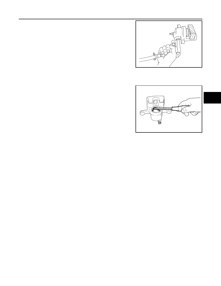
3. Place a wooden block in the cylinder body and blow air into the

hose connection hole to remove the piston and piston boot as

shown.

WARNING:

Do not get your fingers caught between the piston and

wooden block.

4. Remove the piston boot from the piston.

CAUTION:

Do not reuse piston boot.

5. Remove piston seal from cylinder body, using a suitable tool.

CAUTION:

Be careful not to damage cylinder body inner wall.

6. Remove the bleed valve and cap.

CALIPER INSPECTION

Cylinder Body

• Check inside surface of cylinder for score, rust wear, damage or foreign materials. If any of the above condi-

tions are observed, replace cylinder body.

• Minor damage from rust or foreign materials may be eliminated by polishing surface with a fine emery paper.

Replace cylinder body if necessary.

CAUTION:

Use new brake fluid for cleaning. Do not use mineral oils such as gasoline or kerosene. 

Torque Member

Check the torque member for wear, cracks, and damage. If damage or deformation is present, replace the

torque member.

Piston

Check the piston for score, rust, wear, damage or presence of foreign materials. Replace if any of the above

conditions are observed. 

CAUTION:

Piston sliding surface is plated, do not polish with emery paper even if rust or foreign materials are

stuck to sliding surface.

Sliding Pins and Sliding Pin Boots

Check the sliding pins and sliding pin boots for wear, damage, and cracks. If damage or deformation is

present, replace the affected part.

ASSEMBLY

CAUTION:

Use NISSAN Rubber Grease when assembling.
1. Install the bleed valve and cap.

BRD0041D

JPFIA0038ZZ

BR-50

< UNIT DISASSEMBLY AND ASSEMBLY >

REAR DISC BRAKE

2. Apply rubber grease to the new piston seal (1) and insert the

new piston seal (1) into the groove on the cylinder body.

CAUTION:

Do not reuse piston seal.

3. Apply rubber grease to the new piston boot (1). Cover the piston

end (2) with the piston boot (1), and then install the cylinder side

lip on the piston boot (1) securely into the groove on the cylinder

body.

CAUTION:

• Do not reuse piston boot.

• Press pistons in evenly and vary the pressing points to

prevent the cylinder inner wall from being damaged.

4. Install the piston (1) into the cylinder body and insert the piston

boot (2) side lip into the piston groove as shown. 

CAUTION:

Press pistons in evenly and vary the pressing points to pre-

vent the cylinder inner wall from being damaged.

5. Apply rubber grease to the sliding pin boots, then install the sliding pins and sliding pin boots on the torque

member.

6. Install the caliper body on the torque member. Refer to 

BR-39, "Removal and Installation of Brake Caliper

and Disc Rotor"

.

JPFIA0039ZZ

JPFIA0040ZZ

JPFIA0041ZZ

SERVICE DATA AND SPECIFICATIONS (SDS)

BR-51

< SERVICE DATA AND SPECIFICATIONS (SDS) 

C

D

E

G

H

I

J

K

L

M

A

B

BR

N

O

P

SERVICE DATA AND SPECIFICATIONS (SDS)

SERVICE DATA AND SPECIFICATIONS (SDS)

General Specification

INFOID:0000000009484674

Unit: mm (in)

Brake Pedal

INFOID:0000000009484675

Unit: mm (in)

Front brake

Brake model

CLZ33VB

Rotor outer diameter 

× thickness

296 

× 28 (11.654 × 1.102)

Pad length x width x  thickness

140 x 50.5 x 10.0 (5.512 x 1.988 x 0.394)

Cylinder bore diameter (each)

46.4 (1.83)

Rear brake 

Brake model

CLZ14VA

Rotor outer diameter 

× thickness

286 

× 18.0 (11.260 × 0.709)

Pad length 

× width × thickness

87.6 

× 34 × 11.0 (3.449 × 1.339 × 0.433)

Cylinder bore diameter

38.1 (1.50)

Control valve

Valve model

Electric brake force distribution

Brake booster

Booster model

C215T

Diaphragm diameter

215 (8.465)

Recommended brake fluid

Refer to 

MA-12, "Fluids and Lubricants"

.

Pedal free height (H)

M/T

174.7 (6.88)

A/T

182.1 (7.17)

Pedal full stroke (S)

153 (6.02)

Clearance between pedal bracket (C

1

) and threaded end of stop lamp switch and ASCD cancel switch 

(C

2

)

0.74 - 1.96 (0.029 - 0.077)

AWFIA0557ZZ

BR-52

< SERVICE DATA AND SPECIFICATIONS (SDS) 

SERVICE DATA AND SPECIFICATIONS (SDS)

Brake Booster

INFOID:0000000009484676

Unit: mm (in)

Check Valve

INFOID:0000000009484677

Front Disc Brake

INFOID:0000000009484678

Unit: mm (in)

Rear Disc Brake

INFOID:0000000009484679

Unit: mm (in)

Input rod installation length (B)

145 – 152 (5.71 – 5.98)

WFIA0382E

Vacuum leakage 
[at vacuum of -66.7 kPa(-500 mmHg, -19.69 inHg)]

Within 1.3 kPa (10 mmHg, 0.39 inHg) of vacuum for 15 seconds

Brake model

CLZ33VB

Brake pad

Standard thickness (new)

10.0 (0.394)

Minimum thickness

2.0 (0.079)

Disc rotor

Standard thickness (new)

28.0 (1.102)

Minimum thickness

26.0 (1.024)

Maximum uneven wear (measured at 8 positions)

0.015 (0.0006) 

Runout limit (with it attached to the vehicle)

0.05 (0.0020) 

Brake model

CLZ14VA

Brake pad

Standard thickness (new)

11.0 (0.433)

Minimum thickness

2.0 (0.079)

Disc rotor

Standard thickness (new)

18.0 (0.709)

Minimum thickness

16.0 (0.630)

Maximum uneven wear (measured at 8 positions)

0.015 (0.0006) 

Runout limit (with it attached to the vehicle)

0.05 (0.0020) 


Content   ..  83  84  85  86   ..