Nissan Xterra. Manual - part 80
BRAKE BOOSTER
BR-29
< REMOVAL AND INSTALLATION >
C
D
E
G
H
I
J
K
L
M
A
B
BR
N
O
P
REMOVAL
1. Remove the ABS actuator and electric unit (control unit). Refer to
BRC-113, "Removal and Installation"
(type 1),
BRC-234, "Removal and Installation"
(type2).
2. Remove the brake piping from the brake master cylinder.
3. Remove the brake master cylinder and O-ring. Refer to
BR-26, "Removal and Installation"
CAUTION:
Do not reuse O-ring.
4. Remove brake booster vacuum hose from the brake booster. Refer to
BR-31, "Removal and Installation"
5. Remove instrument lower panel LH. Refer to
IP-14, "Removal and Installation"
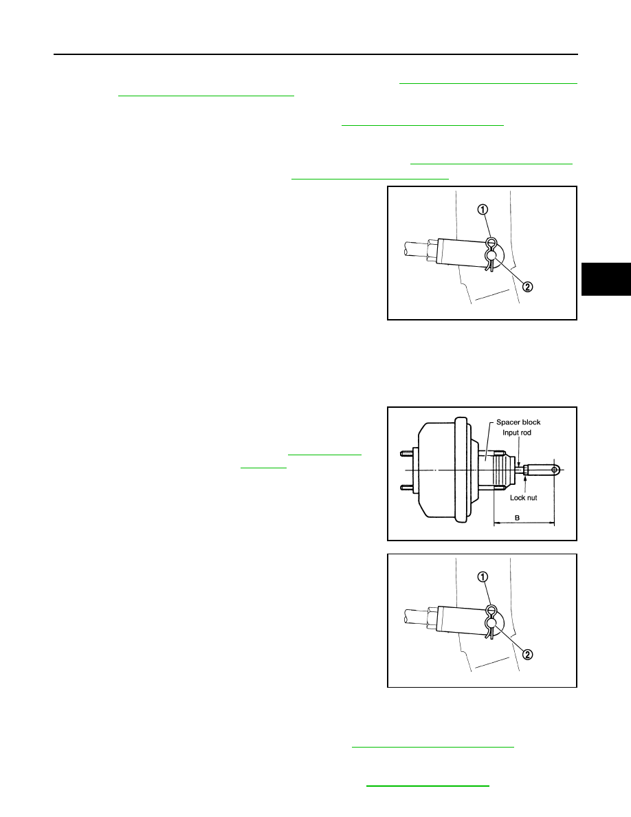
6. Remove the brake pedal clevis pin (2) and snap pin (1) from
inside the vehicle.
7. Remove the brake booster and brake pedal assembly nuts and discard.
CAUTION:
Do not reuse the nuts.
8. Remove brake booster assembly from dash panel.
INSTALLATION
1. Loosen the lock nut to adjust the input rod so that length (B) is
within the specified value.
2. After adjusting input rod length (A), temporarily tighten the lock
nut (1) and install the booster assembly to the dash panel.
• Install gaskets and spacer block between the booster assem-
bly and the dash panel.
3. Connect the input rod using the brake pedal clevis pin (2) and
snap pin (1) from inside the vehicle.
4. Install the brake booster using new nuts.
CAUTION:
Do not reuse the brake booster and brake pedal assembly nuts.
5. Install the brake master cylinder and new O-ring. Refer to
BR-26, "Removal and Installation"
.
CAUTION:
Do not reuse O-ring.
6. Install the brake piping to the brake master cylinder. Refer to
JPFIA0019ZZ
Input rod installation
length (B)
: Refer to
.
WFIA0382E
JPFIA0019ZZ