Nissan Xterra. Manual - part 68
 

  Index      Nissan     Nissan Xterra (2014 year) - Service and Repair Manual


Search            


Content   ..  66  67  68  69   ..


Nissan Xterra. Manual - part 68


BCS

COMBINATION SWITCH OUTPUT CIRCUIT

BCS-31

< DTC/CIRCUIT DIAGNOSIS >

C

D

E

F

G

H

I

J

K

L

B

A

O

P

N

COMBINATION SWITCH OUTPUT CIRCUIT

Diagnosis Procedure

INFOID:0000000009482957

Regarding Wiring Diagram information, refer to 

BCS-44, "Wiring Diagram"

.

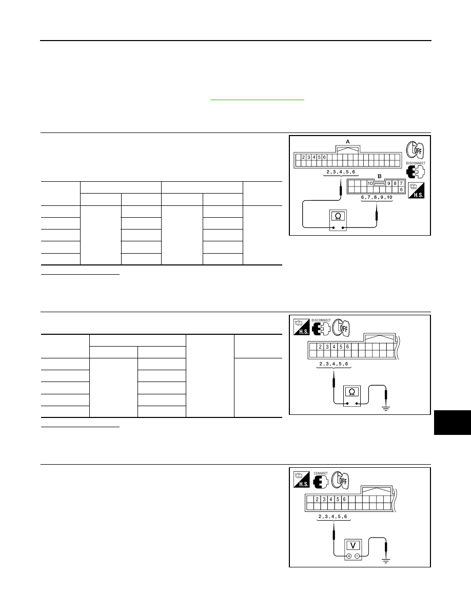
1.

 CHECK OUTPUT 1 - 5 SYSTEM CIRCUIT FOR OPEN

1. Turn ignition switch OFF.

2. Disconnect BCM and combination switch.

3. Check continuity between BCM harness connector and combi-

nation switch harness connector.

Does continuity exist?

YES

>> GO TO 2

NO

>> Repair or replace harness.

2.

 CHECK OUTPUT 1 - 5 SYSTEM CIRCUIT FOR SHORT

Check for continuity between BCM harness connector and ground.

Does continuity exist?

YES

>> Repair or replace harness.

NO

>> GO TO 3

3.

 CHECK BCM INPUT VOLTAGE

1. Connect BCM.

2. Turn ignition switch ON.

3. Check voltage between BCM harness connector and ground.

System

BCM

Combination switch

Continuity

Connector

Terminal

Connector

Terminal

OUTPUT 1

M18

(A)

6

M28

(B)

6

Yes

OUTPUT 2

5

7

OUTPUT 3

4

10

OUTPUT 4

3

9

OUTPUT 5

2

8

ALMIA0275ZZ

System

BCM

Ground

Continuity

Connector

Terminal

OUTPUT 1

M18

6

No

OUTPUT 2

5

OUTPUT 3

4

OUTPUT 4

3

OUTPUT 5

2

ALMIA0276ZZ

ALMIA0277ZZ

BCS-32

< DTC/CIRCUIT DIAGNOSIS >

COMBINATION SWITCH OUTPUT CIRCUIT

Is the measurement value normal?

YES

>> GO TO 4

NO

>> Replace BCM. Refer to 

BCS-50, "Removal and Installation"

.

4.

 CHECK COMBINATION SWITCH

Check combination switch. Refer to 

BCS-48, "Symptom Table"

.

Is the check result normal?

YES

>> Replace BCM. Refer to 

BCS-50, "Removal and Installation"

.

NO

>> Replace the combination switch (applicable parts). Refer to 

EXL-161, "Removal and Installation"

.

Special Repair Requirement

INFOID:0000000009482958

1.

 ADDITIONAL SERVICE WHEN REPLACING BCM

>> Refer to 

BCS-3, "ADDITIONAL SERVICE WHEN REPLACING CONTROL UNIT : Description"

.

System

Terminals

Voltage

(Approx.)

(+)

(

−)

BCM

Ground

Connector

Terminal

INPUT 1

M18

6

Refer to 

BCS-

36, "Physical 

Values"

.

INPUT 2

5

INPUT 3

4

INPUT 4

3

INPUT 5

2

BCS

BCM (BODY CONTROL MODULE)

BCS-33

< ECU DIAGNOSIS INFORMATION >

C

D

E

F

G

H

I

J

K

L

B

A

O

P

N

ECU DIAGNOSIS INFORMATION

BCM (BODY CONTROL MODULE)

Reference Value

INFOID:0000000009482959

NOTE:

The Signal Tech II Tool (J-50190) can be used to perform the following functions. Refer to the Signal Tech II

User Guide for additional information.

• Activate and display TPMS transmitter IDs

• Display tire pressure reported by the TPMS transmitter

• Read TPMS DTCs

• Register TPMS transmitter IDs

VALUES ON THE DIAGNOSIS TOOL

Monitor Item

Condition

Value/Status

ACC ON SW

Ignition switch OFF or ON

Off

Ignition switch ACC

On

AIR COND SW

A/C switch OFF

Off

A/C switch ON

On

AIR PRESS FL

Front left tire air pressure value

kPa, kg/cm

2

, psi

AIR PRESS FR

Front right tire air pressure value

kPa, kg/cm

2

, psi

AIR PRESS RL

Rear left tire air pressure value

kPa, kg/cm

2

, psi

AIR PRESS RR

Rear right tire air pressure value

kPa, kg/cm

2

, psi

AUTO LIGHT SW

Lighting switch OFF

Off

Lighting switch AUTO

On

BACK DOOR SW

Back door closed

Off

Back door opened

On

BRAKE SW

Brake pedal released

Off

Brake pedal applied

On

BUCKLE SW

Seat belt buckle unfastened

Off

Seat belt buckle fastened

On

BUZZER

Buzzer in combination meter OFF

Off

Buzzer in combination meter ON

On

CARGO LAMP SW

Cargo lamp switch OFF

Off

Cargo lamp switch ON

On

CDL LOCK SW

Door lock/unlock switch does not operate

Off

Press door lock/unlock switch to the LOCK side

On

CDL UNLOCK SW

Door lock/unlock switch does not operate

Off

Press door lock/unlock switch to the UNLOCK side

On

DOOR SW-AS

Front door RH closed

Off

Front door RH opened

On

DOOR SW-DR

Front door LH closed

Off

Front door LH opened

On

DOOR SW-RL

Rear door LH closed

Off

Rear door LH opened

On

DOOR SW-RR

Rear door RH closed

Off

Rear door RH opened

On

BCS-34

< ECU DIAGNOSIS INFORMATION >

BCM (BODY CONTROL MODULE)

ENGINE RUN  

Engine stopped 

Off

Engine running

On

FAN ON SIG

Blower motor fan switch OFF

Off

Blower motor fan switch ON

On

FR FOG SW

Front fog lamp switch OFF

Off

Front fog lamp switch ON

On

FR WASHER SW

Front washer switch OFF

Off

Front washer switch ON

On

FR WIPER LOW

Front wiper switch OFF

Off

Front wiper switch LO

On

FR WIPER HI

Front wiper switch OFF

Off

Front wiper switch HI

On

FR WIPER INT

Front wiper switch OFF

Off

Front wiper switch INT

On

FR WIPER STOP

Any position other than front wiper stop position

Off

Front wiper stop position

On

HAZARD SW

When hazard switch is not pressed

Off

When hazard switch is pressed

On

HEAD LAMP SW 1

Headlamp switch OFF

Off

Headlamp switch 1st

On

HEAD LAMP SW 2

Headlamp switch OFF

Off

Headlamp switch 1st

On

HI BEAM SW

High beam switch OFF

Off

High beam switch HI

On

ID REGST FL1

ID registration of front left tire incomplete

YET

ID registration of front left tire complete

DONE

ID REGST FR1

ID registration of front right tire incomplete

YET

ID registration of front right tire complete

DONE

ID REGST RL1

ID registration of rear left tire incomplete

YET

ID registration of rear left tire complete

DONE

ID REGST RR1

ID registration of rear right tire incomplete

YET

ID registration of rear right tire complete

DONE

IGN ON SW

Ignition switch OFF or ACC

Off

Ignition switch ON

On

IGN SW CAN

Ignition switch OFF or ACC

Off

Ignition switch ON

On

INT VOLUME

Wiper intermittent dial is in a dial position 1 - 7

1 - 7

KEY CYL LK-SW

Door key cylinder LOCK position

Off

Door key cylinder other than LOCK position

On

KEY CYL UN-SW

Door key cylinder UNLOCK position

Off

Door key cylinder other than UNLOCK position

On

KEY ON SW

Mechanical key is removed from key cylinder

Off

Mechanical key is inserted to key cylinder

On

Monitor Item

Condition

Value/Status


Content   ..  66  67  68  69   ..