Nissan March K13. Manual - part 499
PCS-78
< DTC/CIRCUIT DIAGNOSIS >
[POWER DISTRIBUTION SYSTEM]
B2616 IGNITION RELAY CIRCUIT
YES
>> Replace BCM. Refer to
BCS-57, "Removal and Installation"
NO
>> Repair or replace harness.
3.
CHECK IGNITION RELAY GROUND CIRCUIT
1.
Turn ignition switch OFF.
2.
Check continuity between ignition relay harness connector and ground.
Is the inspection result normal?
YES
>> GO TO 4.
NO
>> Repair ignition relay ground circuit.
4.
CHECK IGNITION RELAY POWER SUPPLY CIRCUIT-2
1.
Turn ignition switch ON.
2.
Check voltage between ignition relay harness connector and ground.
Is the inspection result normal?
YES
>> GO TO 5.
NO
>> Check continuity open or short between ignition relay and battery.
5.
CHECK IGNITION RELAY
PCS-78, "Component Inspection"
.
Is the inspection result normal?
YES
>> GO TO 6.
NO
>> Replace ignition relay.
6.
CHECK INTERMITTENT INCIDENT
GI-33, "Intermittent Incident"
>> INSPECTION END
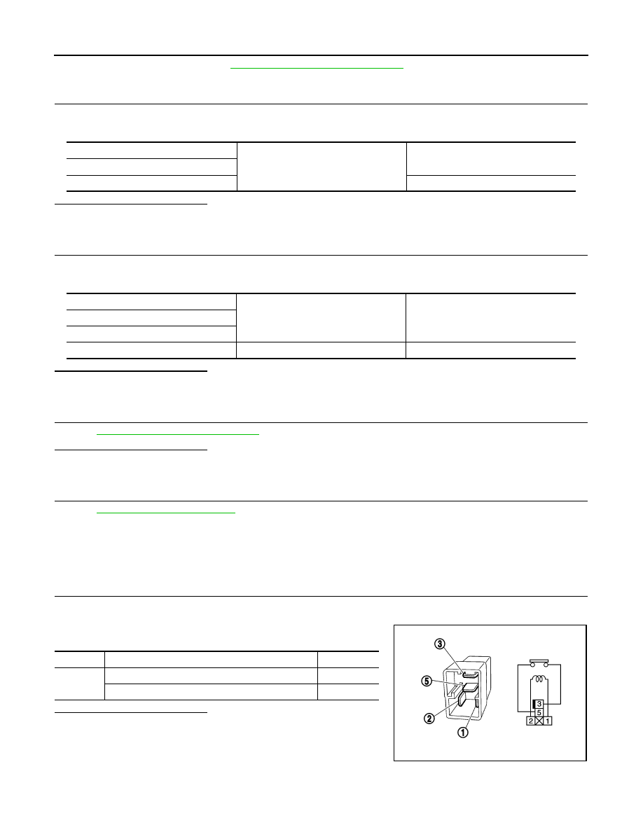
Component Inspection
INFOID:0000000005998925
1.
CHECK IGNITION RELAY
1.
Turn ignition switch OFF.
2.
Remove ignition relay.
3.
Check the continuity between ignition relay terminals.
Is the inspection result normal?
YES
>> INSPECTION END
NO
>> Replace Ignition relay
Ignition relay
Ground
Continuity
Terminal
1
Existed
(+)
(–)
Voltage (V)
(Approx.)
Ignition relay
Terminal
5
Ground
Battery voltage
Terminals
Condition
Continuity
3 and 5
12 V direct current supply between terminals 1 and 2
Existed
No current supply
Not existed
PBIB0098E