Nissan March K13. Manual - part 484
PCS-18
< ECU DIAGNOSIS INFORMATION >
[IPDM E/R (WITH I-KEY)]
IPDM E/R
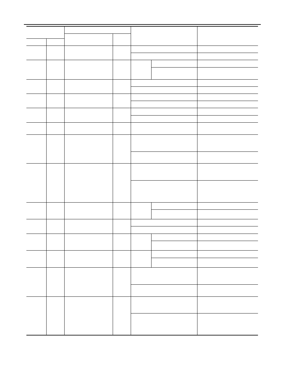
23
(SB)
Ground
Horn relay control
Output
The horn is deactivated
Battery voltage
The horn is activated
0 V
24
(V)
Ground
Front wiper stop position
Input
Ignition
switch
ON
Front wiper stop position
0 V
Any position other than
front wiper stop position
Battery voltage
27
(SB)
Ground
Ignition relay power sup-
ply
Output
Ignition switch OFF
0 V
Ignition switch ON
Battery voltage
30
(R)
Ground
Starter motor
Output
Ignition switch ON
0 V
At engine cranking
Battery voltage
31
(P)
Ground
Cooling fan relay power
supply
Output
Cooling fan OFF
0 V
Cooling fan operated
Battery voltage
32
(G)
Ground
Battery power supply
Input
Ignition switch OFF
Battery voltage
33
(BR)
Ground
Fuel pump
Output
• Approximately 1 second after
turning the ignition switch ON
• Engine running
0 - 1.5 V
Approximately 1 second or more af-
ter turning the ignition switch ON
Battery voltage
35
(G)
Ground
ECM relay power supply
Output
Ignition switch OFF
(More than a few seconds after turn-
ing ignition switch OFF)
0 V
• Ignition switch ON
• Ignition switch OFF
(For a few seconds after turning
ignition switch OFF)
Battery voltage
38
(L)
Ground
Headlamp LO (LH)
Output
Ignition
switch
ON
Lighting switch OFF
0 V
Lighting switch 2ND
Battery voltage
39
(LG)
Ground
Starter relay
Output
Ignition switch ON
0 V
At engine cranking
Battery voltage
40
(P)
Ground
Headlamp LO (RH)
Output
Ignition
switch
ON
Lighting switch OFF
0 V
Lighting switch 2ND
Battery voltage
42
(LG)
Ground
Oil pressure switch
Input
Ignition
switch
ON
Engine stopped
0 V
Engine running
Battery voltage
43
(GR)
Ground
Fuel pump relay control
Output
• Approximately 1 second after
turning the ignition switch ON
• Engine running
0 - 1.0 V
Approximately 1 second or more af-
ter turning the ignition switch ON
Battery voltage
47
(R/W)
Ground
ECM power supply
Output
Ignition switch OFF
(More than a few seconds after turn-
ing ignition switch OFF)
0 V
• Ignition switch ON
• Ignition switch OFF
(For a few seconds after turning
ignition switch OFF)
Battery voltage
Terminal NO.
(Wire color)
Description
Condition
Value
(Approx.)
Signal name
Input/
Output
+
–