Nissan March K13. Manual - part 468
MWI-10
< SYSTEM DESCRIPTION >
SYSTEM
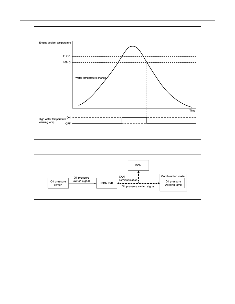
TIMING CHART
OIL PRESSURE WARNING LAMP
OIL PRESSURE WARNING LAMP : System Diagram
INFOID:0000000005883858
OIL PRESSURE WARNING LAMP : System Description
INFOID:0000000005883859
• IPDM E/R reads the ON/OFF signals from the oil pressure switch and transmits the oil pressure switch sig-
nal to the BCM via CAN communication.
• BCM transmits oil pressure switch signal to the combination meter via CAN communication.
• The combination meter turns the oil pressure warning lamp ON (at the time of a reduction in hydraulic pres-
sure)/OFF (except at the time of a reduction in hydraulic pressure) according to the oil pressure switch signal
received via CAN communication.
METER ILLUMINATION CONTROL
JSNIA2969GB
JSNIA2464GB