Nissan March K13. Manual - part 392
HAC-102
< DTC/CIRCUIT DIAGNOSIS >
[MANUAL AIR CONDITIONER]
BLOWER MOTOR
YES
>> GO TO 6.
NO
>> Repair the harness or connector.
6.
CHECK VOLTAGE BETWEEN BLOWER FAN RESISTOR AND GROUND
1.
Disconnect the blower fan resistor connector.
2.
Turn the ignition switch ON.
3.
Check voltage between blower fan resistor harness connector and the ground.
Is the inspection result normal?
YES
>> GO TO 7.
NO
>> Repair the harness or connector between blower fan resistor and blower motor.
7.
CHECK BLOWER FAN RESISTOR
1.
Turn the ignition switch OFF.
2.
Perform the component inspection of blower fan resistor. Refer to
HAC-102, "Component Inspection"
Is the inspection result normal?
YES
>> GO TO 8.
NO
>> Replace the blower fan resistor.
8.
CHECK CIRCUIT CONTINUITY BETWEEN A/C CONTROL AND BLOWER FAN RESISTOR
Check continuity between A/C control harness connector and blower fan resistor.
Is the inspection result normal?
YES
>> Replace A/C control.
NO
>> Repair the harness or connector.
Component Inspection
INFOID:0000000006024121
BLOWER MOTOR
1.
CHECK BLOWER MOTOR
1.
Remove the blower motor. Refer to
XX-XX, "*****"
.
2.
Check that there is not any mixing foreign object in the blower motor.
Is the inspection result normal?
YES
>> GO TO 2.
NO
>> Replace the blower motor.
2.
CHECK BLOWER MOTOR
Check that there is not breakage or damage in the blower motor.
Is the inspection result normal?
YES
>> GO TO 3.
NO
>> Replace the blower motor.
3.
CHECK BLOWER MOTOR
Check that the blower motor turns smoothly.
Is the inspection result normal?
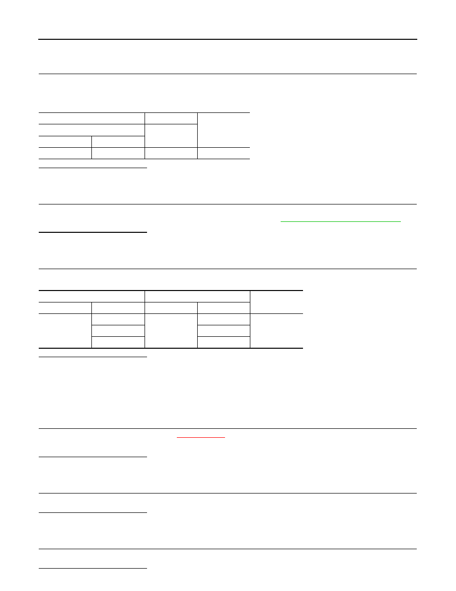
(+)
(
−
)
Voltage
(Approx.)
Blower fan resistor
—
Connector
Terminal
M104
1
Ground
12 V
A/C control
Blower fan resistor
Continuity
Connector
Terminal
Connector
Terminal
M53
2
M104
2
Existed
3
3
4
4