Nissan March K13. Manual - part 250
P1805 BRAKE SWITCH
EC-461
< DTC/CIRCUIT DIAGNOSIS >
[HR12DE (TYPE 2)]
C
D
E
F
G
H
I
J
K
L
M
A
EC
N
P
O
P1805 BRAKE SWITCH
DTC Logic
INFOID:0000000006037381
DTC DETECTION LOGIC
DTC CONFIRMATION PROCEDURE
1.
PERFORM DTC CONFIRMATION PROCEDURE
1.
Turn ignition switch ON.
2.
Fully depress the brake pedal for at least 5 seconds.
3.
Erase DTC.
4.
Check 1st trip DTC.
Is 1st trip DTC detected?
YES
>> Go to
NO
>> INSPECTION END
Diagnosis Procedure
INFOID:0000000006037382
1.
CHECK STOP LAMP SWITCH CIRCUIT
1.
Turn ignition switch OFF.
2.
Check the stop lamp when depressing and releasing the brake pedal.
Is the inspection result normal?
YES
>> GO TO 4.
NO
>> GO TO 2.
2.
CHECK STOP LAMP SWITCH POWER SUPPLY CIRCUIT
1.
Turn ignition switch OFF.
2.
Disconnect stop lamp switch harness connector.
3.
Check the voltage between stop lamp switch harness connector and ground.
Is the inspection result normal?
YES
>> GO TO 4.
NO
>> GO TO 3.
3.
DETECT MALFUNCTIONING PART
Check harness for open or short between stop lamp switch and battery.
>> Repair open circuit or short to ground or short to power in harness or connectors.
4.
CHECK STOP LAMP SWITCH INPUT SIGNAL CIRCUIT FOR OPEN AND SHORT
1.
Disconnect stop lamp switch harness connector.
2.
Disconnect ECM harness connector.
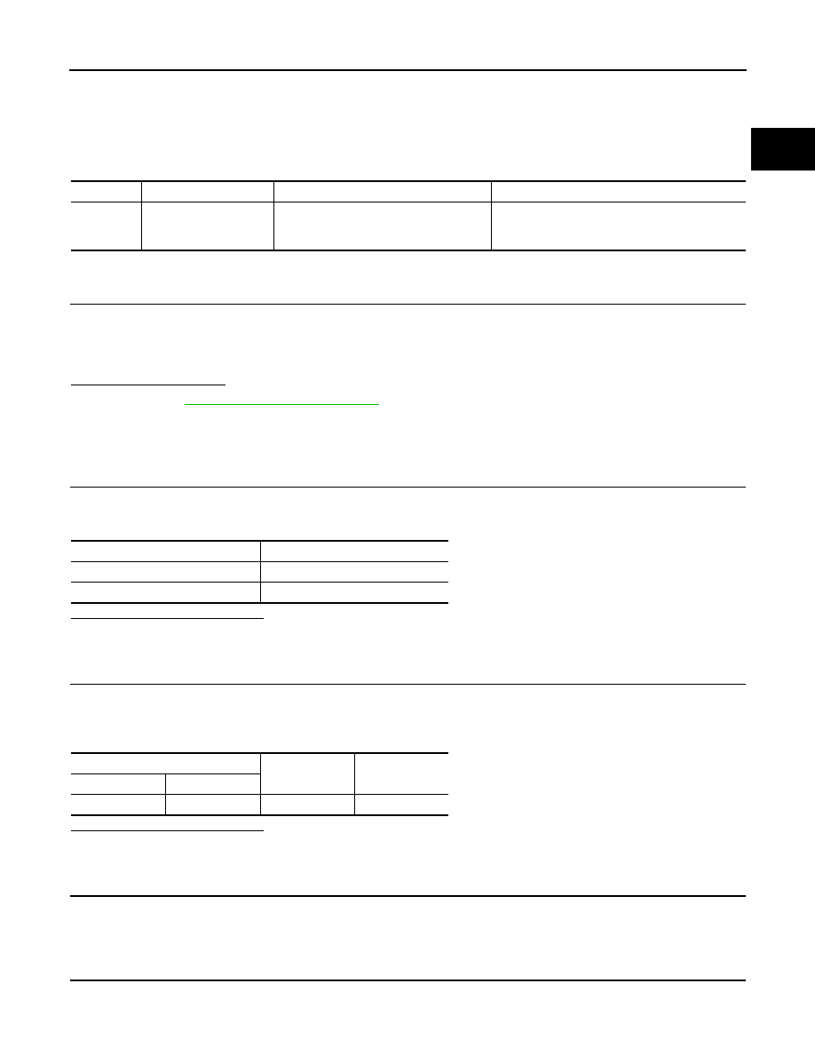
DTC No.
Trouble diagnosis name
DTC detecting condition
Possible cause
P1805
Brake switch
A brake switch signal is not sent to ECM
for extremely long time while the vehicle is
driving.
• Harness or connectors
(Stop lamp switch circuit is open or shorted.)
• Stop lamp switch
Brake pedal
Stop lamp
Fully released
Not illuminated
Slightly depressed
Illuminated
Stop lamp switch
Ground
Voltage
Connector
Terminal
E114
1
Ground
Battery voltage