Nissan March K13. Manual - part 225
ECM
EC-361
< ECU DIAGNOSIS INFORMATION >
[HR12DE (TYPE 2)]
C
D
E
F
G
H
I
J
K
L
M
A
EC
N
P
O
30
(P)
28
(B)
Manifold absolute pressure
(MAP) sensor
Output
[Engine is running]
• Warm-up condition
• Both A/C switch and blower fan
switch: ON (Compressor operates)
4.5 V
Output voltage varies with atmo-
spheric pressure.
[Engine is running]
• Warm-up condition
• Idle speed
1.5 V
[Engine is running]
• Warm-up condition
• Engine speed: 2,000 rpm
1.2 V
31
(P)
28
(B)
Intake air temperature sen-
sor
Input
[Engine is running]
0 - 4.8 V
Output voltage varies with intake
air temperature.
33
(SB)
35
(P)
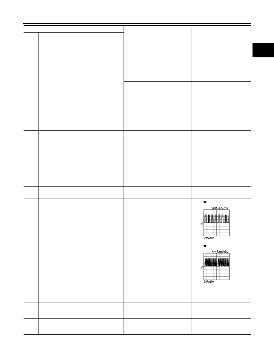
Heated oxygen sensor 1
—
[Engine is running]
• Warm-up condition
• Engine speed: 2,000 rpm
0 - 1.0 V
(Periodically change)
34
(W)
36
(B)
Heated oxygen sensor 2
Input
[Engine is running]
• Revving engine from idle to 3,000
rpm quickly after the following condi-
tions are met
- Engine: after warming up
- Keeping the engine speed between
3,500 and 4,000 rpm for 1 minute
and at idle for 1 minute under no
load
0 - 1.0 V
35
(P)
—
Sensor ground
(Heated oxygen sensor 1)
—
—
—
36
(B)
—
Sensor ground
(Heated oxygen sensor 2)
—
—
—
37
(W)
39
(R)
Crankshaft position sensor
(POS)
Input
[Engine is running]
• Warm-up condition
• Idle speed
NOTE:
The pulse cycle changes depending
on rpm at idle
4.0 V
[Engine is running]
• Engine speed: 2,000 rpm
4.0 V
38
(W)
27
(BR)
Sensor power supply
(Refrigerant pressure sen-
sor)
—
[Ignition switch: ON]
5 V
39
(R)
—
Sensor ground
[Crankshaft position sensor
(POS)]
—
—
—
40
(BR)
—
Sensor ground
[Camshaft position sensor
(PHASE)]
—
—
—
Terminal No.
Description
Condition
Value
(Approx.)
+
–
Signal name
Input/
Output
JSBIA0395GB
JSBIA0396GB