Nissan March K13. Manual - part 152
ECM
EC-69
< ECU DIAGNOSIS INFORMATION >
[HR12DE (TYPE 1)]
C
D
E
F
G
H
I
J
K
L
M
A
EC
N
P
O
4
(P)
107
(B)
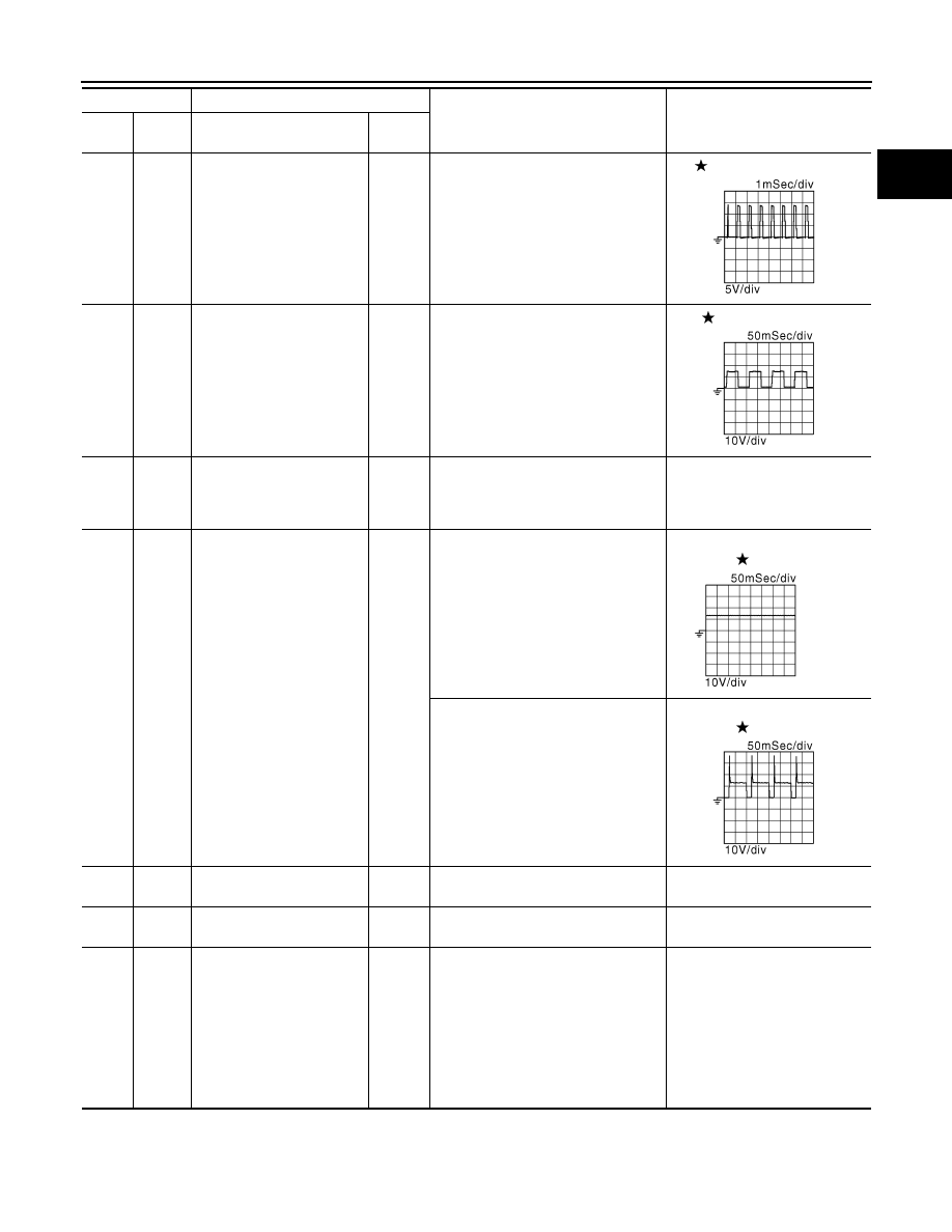
Throttle control motor
(Close)
Output
[Ignition switch: ON]
• Engine stopped
• Shift lever: 1st position
• Accelerator pedal: Fully released
2 V
5
(G)
107
(B)
Heated oxygen sensor 2
heater
Output
[Engine is running]
• Engine speed: Below 3,900 rpm af-
ter the following conditions are met
- Engine: after warming up
- Keeping the engine speed between
3,500 and 4,000 rpm for 1 minute
and at idle for 1 minute under no
load
10 V
[Ignition switch: ON]
• Engine stopped
[Engine is running]
• Engine speed: Above 3,900 rpm
BATTERY VOLTAGE
(11 - 14 V)
9
(P)
107
(B)
EVAP canister purge volume
control solenoid valve
Output
[Engine is running]
• Idle speed
• Accelerator pedal is not depressed
even slightly, after engine starting
BATTERY VOLTAGE
(11 - 14 V)
[Engine is running]
• Engine speed: About 2,000 rpm
(More than 100 seconds after start-
ing engine.)
BATTERY VOLTAGE
(11 - 14 V)
10
(B)
—
ECM ground
—
—
—
11
(B)
—
ECM ground
—
—
—
12
(R)
107
(B)
EGR volume control valve
(step 1)
Output
[Engine is running]
• Idle speed
0.5 V or BATTERY VOLTAGE (11
- 14 V)
Output voltage varies with EGR
volume control valve opening an-
gle (step).
16
(LG)
EGR volume control valve
(step 3)
20
(G)
EGR volume control valve
(step 2)
24
(SB)
EGR volume control valve
(step 4)
Terminal No.
Description
Condition
Value
(Approx.)
+
–
Signal name
Input/
Output
JMBIA0215GB
JMBIA0214GB
JMBIA0039GB
JMBIA0216GB