Nissan March K13. Manual - part 137


  Index      Nissan     Nissan March K13 - Service and Repair Manual)


Search            


Content   ..  135  136  137  138   ..


Nissan March K13. Manual - part 137


APPLICATION NOTICE

EC-9

< HOW TO USE THIS MANUAL >

[HR12DE (TYPE 1)]

C

D

E

F

G

H

I

J

K

L

M

A

EC

N

P

O

HOW TO USE THIS MANUAL

APPLICATION NOTICE

How to Check Vehicle Type

INFOID:0000000006022900

Check the vehicle type to confirm the service information in EC section.

NOTE:
• L-jetronic is a fuel injection control method that the mass air flow sensor mounted on the air cleaner case

directly measures air volume taken into the engine (cylinder) and determines the fundamental fuel injection
amount.

• D-jetronic is a fuel injection control method to calculate air volume taken into the engine (cylinder) and deter-

mine the fundamental fuel injection amount, based on a throttle angle and an intake air pressure calculated
by the manifold absolute pressure sensor mounted on the intake manifold.
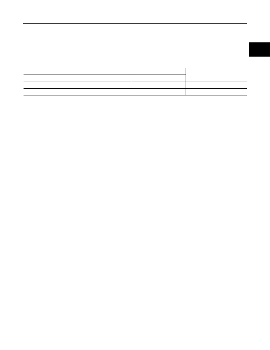
Vehicle type

Service information

Destination

Transmission

Engine control

For Thailand

M/T

L-jetronic

HR12DE (TYPE 1)

Except for Thailand

A/T, M/T

D-jetronic

HR12DE (TYPE 2)

EC-10

< PRECAUTION >

[HR12DE (TYPE 1)]

PRECAUTIONS

PRECAUTION

PRECAUTIONS

Precaution for Supplemental Restraint System (SRS) "AIR BAG" and "SEAT BELT 
PRE-TENSIONER"

INFOID:0000000005989135

The Supplemental Restraint System such as “AIR BAG” and “SEAT BELT PRE-TENSIONER”, used along
with a front seat belt, helps to reduce the risk or severity of injury to the driver and front passenger for certain
types of collision. This system includes seat belt switch inputs and dual stage front air bag modules. The SRS
system uses the seat belt switches to determine the front air bag deployment, and may only deploy one front
air bag, depending on the severity of a collision and whether the front occupants are belted or unbelted.
Information necessary to service the system safely is included in the “SRS AIR BAG” and “SEAT BELT” of this
Service Manual.

WARNING:

• To avoid rendering the SRS inoperative, which could increase the risk of personal injury or death in

the event of a collision that would result in air bag inflation, all maintenance must be performed by
an authorized NISSAN/INFINITI dealer.

• Improper maintenance, including incorrect removal and installation of the SRS, can lead to personal

injury caused by unintentional activation of the system. For removal of Spiral Cable and Air Bag
Module, see the “SRS AIR BAG”.

• Do not use electrical test equipment on any circuit related to the SRS unless instructed to in this

Service Manual. SRS wiring harnesses can be identified by yellow and/or orange harnesses or har-
ness connectors.

PRECAUTIONS WHEN USING POWER TOOLS (AIR OR ELECTRIC) AND HAMMERS

WARNING:

• When working near the Air Bag Diagnosis Sensor Unit or other Air Bag System sensors with the

ignition ON or engine running, DO NOT use air or electric power tools or strike near the sensor(s)
with a hammer. Heavy vibration could activate the sensor(s) and deploy the air bag(s), possibly
causing serious injury.

• When using air or electric power tools or hammers, always switch the ignition OFF, disconnect the

battery, and wait at least 3 minutes before performing any service.

Precaution for Procedure without Cowl Top Cover

INFOID:0000000005989136

When performing the procedure after removing cowl top cover, cover
the lower end of windshield with urethane, etc.

On Board Diagnostic (OBD) System of Engine

INFOID:0000000005989137

The ECM has an on board diagnostic system. It will light up the malfunction indicator lamp (MIL) to warn the
driver of a malfunction causing emission deterioration.

CAUTION:

• Be sure to turn the ignition switch OFF and disconnect the negative battery cable before any repair

or inspection work. The open/short circuit of related switches, sensors, solenoid valves, etc. will
cause the MIL to light up.

• Be sure to connect and lock the connectors securely after work. A loose (unlocked) connector will

cause the MIL to light up due to the open circuit. (Be sure the connector is free from water, grease,
dirt, bent terminals, etc.)

PIIB3706J

PRECAUTIONS

EC-11

< PRECAUTION >

[HR12DE (TYPE 1)]

C

D

E

F

G

H

I

J

K

L

M

A

EC

N

P

O

• Certain systems and components, especially those related to OBD, may use a new style slide-lock-

ing type harness connector. For description and how to disconnect, refer to 

PG-4, "Harness Connec-

tor"

.

• Be sure to route and secure the harnesses properly after work. The interference of the harness with

a bracket, etc. may cause the MIL to light up due to the short circuit.

• Be sure to connect rubber tubes properly after work. A misconnected or disconnected rubber tube

may cause the MIL to light up due to the malfunction of the fuel injection system, etc.

• Be sure to erase the unnecessary malfunction information (repairs completed) from the ECM and

TCM (Transmission control module) before returning the vehicle to the customer.

General Precautions

INFOID:0000000005989138

• Always use a 12 volt battery as power source.
• Do not attempt to disconnect battery cables while engine is

running.

• Before connecting or disconnecting the ECM harness con-

nector, turn ignition switch OFF and disconnect negative bat-
tery cable. Failure to do so may damage the ECM because
battery voltage is applied to ECM even if ignition switch is
turned OFF.

• Before removing parts, turn ignition switch OFF and then dis-

connect battery ground cable.

• Do not disassemble ECM.
• If a battery cable is disconnected, the memory will return to

the ECM value.
The ECM will now start to self-control at its initial value. So,
engine operation can vary slightly in this case. However, this
is not an indication of a malfunction. Do not replace parts
because of a slight variation.

• If the battery is disconnected, the following emission-related

diagnostic information will be lost within 24 hours.

Diagnostic trouble codes
1st trip diagnostic trouble codes
Freeze frame data
1st trip freeze frame data
System readiness test (SRT) codes
Test values
• When connecting ECM harness connector (A), fasten (B) it

securely with a lever as far as it will go as shown in the figure.

SEF289H

1.

ECM

C.

Loosen

PBIA9222J

JMBIA0029ZZ

EC-12

< PRECAUTION >

[HR12DE (TYPE 1)]

PRECAUTIONS

• When connecting or disconnecting pin connectors into or

from ECM, take care not to damage pin terminals (bend or
break).
Make sure that there are not any bends or breaks on ECM pin
terminal, when connecting pin connectors.

• Securely connect ECM harness connectors.

A poor connection can cause an extremely high (surge) volt-
age to develop in coil and condenser, thus resulting in dam-
age to ICs.

• Keep engine control system harness at least 10 cm (4 in) away

from adjacent harness, to prevent engine control system mal-
functions due to receiving external noise, degraded operation
of ICs, etc.

• Keep engine control system parts and harness dry.
• Before replacing ECM, perform ECM Terminals and Reference

Value inspection and make sure ECM functions properly.
Refer to 

EC-65, "Reference Value"

.

• Handle mass air flow sensor carefully to avoid damage.
• Do not clean mass air flow sensor with any type of detergent.
• Do not disassemble electric throttle control actuator.
• Even a slight leak in the air intake system can cause serious

incidents.

• Do not shock or jar the camshaft position sensor (PHASE),

crankshaft position sensor (POS).

• After performing each TROUBLE DIAGNOSIS, perform DTC

CONFIRMATION PROCEDURE or Component Function
Check.
 The DTC should not be displayed in the DTC CONFIRMA-
TION PROCEDURE if the repair is completed. The Component
Function Check should be a good result if the repair is completed.

PBIB0090E

MEF040D

SAT652J


Content   ..  135  136  137  138   ..