Nissan March K13. Manual - part 100
HOOD
DLK-111
< REMOVAL AND INSTALLATION >
[WITH INTELLIGENT KEY SYSTEM]
C
D
E
F
G
H
I
J
L
M
A
B
DLK
N
O
P
REMOVAL AND INSTALLATION
HOOD
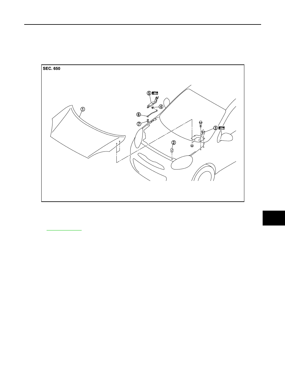
Exploded View
INFOID:0000000005948964
HOOD ASSEMBLY
HOOD ASSEMBLY : Removal and Installation
INFOID:0000000005948965
CAUTION:
• Operate with two workers, because of its heavy weight.
• Use protective tape or shop cloth to protect from damage during removal and installation.
REMOVAL
1.
Support hood assembly with the proper material to prevent it from falling.
WARNING:
Injury may occur if hood assembly is not supported by the proper material when removing hood
assembly.
2.
Remove hood hinge mounting nuts on the hood to remove the hood assembly.
INSTALLATION
Install in the reverse order of removal.
CAUTION:
• Check hood hinge rotating part for poor lubrication. If necessary, apply body grease.
• After installation, apply touch-up paint (the body color) onto the heads of hood hinge mounting bolts
and nuts.
1.
Hood assembly
2.
Hood bumper rubber
3.
Hood hinge (LH)
4.
Grommet
5.
Hood hinge (RH)
6.
Hood support rod
7.
Clamp
Refer to
JMKIA5289ZZ