Nissan March K13. Manual - part 86
B2627 OUTSIDE ANTENNA
DLK-55
< DTC/CIRCUIT DIAGNOSIS >
[WITH INTELLIGENT KEY SYSTEM]
C
D
E
F
G
H
I
J
L
M
A
B
DLK
N
O
P
3.
Check continuity between BCM harness connector and ground.
Is the inspection result normal?
YES
>> GO TO 3.
NO
>> Repair or replace harness.
3.
CHECK OUTSIDE KEY ANTENNA INPUT SIGNAL 2
1.
Replace outside key antenna (passenger side). (New antenna or other antenna)
2.
Connect BCM connector and outside key antenna (passenger side) connector.
3.
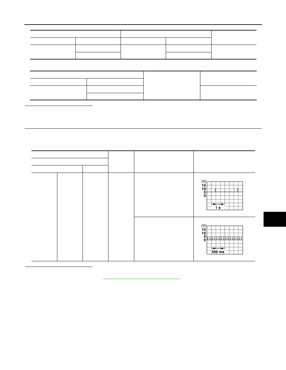
Check signal between BCM harness connector and ground using oscilloscope.
Is the inspection result normal?
YES
>> Replace outside key antenna (passenger side).
NO
>> Replace BCM. Refer to
BCS-57, "Removal and Installation"
BCM
Outside key antenna (passenger side)
Continuity
Connector
Terminal
Connector
Terminal
M71
80
D12
1
Existed
81
2
BCM
Ground
Continuity
Connector
Terminal
M71
80
Not existed
81
(+)
(–)
Condition
Signal
(Reference value)
BCM
Connector
Terminal
Passenger
side
M71
80, 81
Ground
When Intelligent Key is in the
antenna detection area
When Intelligent Key is not in
the antenna detection area
JMKIA3839GB
JMKIA3838GB