Almera Tino V10 (2003 year). Manual - part 208
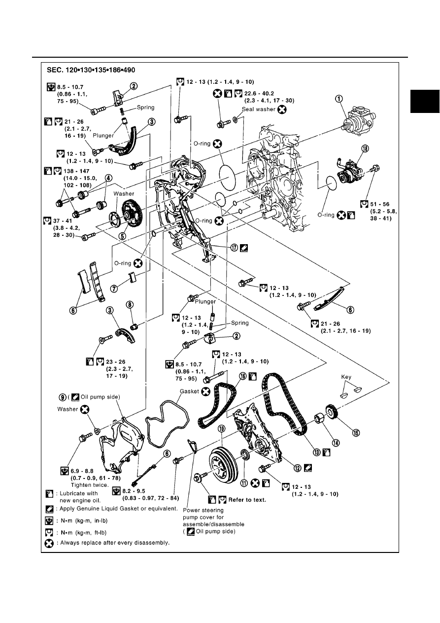
PRIMARY TIMING CHAIN
EM-177
[YD]
C
D
E
F
G
H
I
J
K
L
M
A
EM
MBIA0027E
1.
Fuel pump
2.
Chain tensioner
3.
Slack guide
4.
Camshaft sprocket
5.
Fuel pump sprocket
6.
Tension guide
|
|
|
PRIMARY TIMING CHAIN EM-177 [YD] C D E F G H I J K L M A EM MBIA0027E 1. Fuel pump 2. Chain tensioner 3. Slack guide 4. Camshaft sprocket 5. Fuel pump sprocket 6. Tension guide |