Almera Tino V10 (2003 year). Manual - part 97
ENGINE CONTROL SYSTEM
EC-571
[QG (WITHOUT EURO-OBD)]
C
D
E
F
G
H
I
J
K
L
M
A
EC
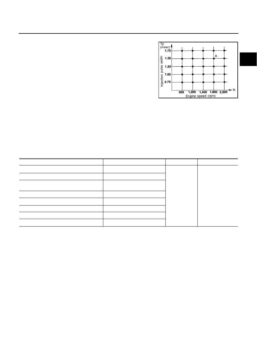
SYSTEM DESCRIPTION
The ignition timing is controlled by the ECM to maintain the best air-
fuel ratio for every running condition of the engine. The ignition tim-
ing data is stored in the ECM. This data forms the map shown.
The ECM receives information such as the injection pulse width and
camshaft position sensor signal. Computing this information, ignition
signals are transmitted to the power transistor.
e.g., N: 1,800 rpm, Tp: 1.50 msec
A
°
BTDC
During the following conditions, the ignition timing is revised by the
ECM according to the other data stored in the ECM.
●
At starting
●
During warm-up
●
At idle
●
At low battery voltage
●
During acceleration
The knock sensor retard system is designed only for emergencies. The basic ignition timing is programmed
within the anti-knocking zone, if recommended fuel is used under dry conditions. The retard system does not
operate under normal driving conditions. If engine knocking occurs, the knock sensor monitors the condition.
The signal is transmitted to the ECM. The ECM retards the ignition timing to eliminate the knocking condition.
Air Conditioning Cut Control
EBS00QUT
INPUT/OUTPUT SIGNAL CHART
*1: These signals are sent to the ECM through CAN communication line.
*2: The ECM determines the start signal status by the signals of engine speed and battery voltage.
SYSTEM DESCRIPTION
This system improves engine operation when the air conditioner is used.
Under the following conditions, the air conditioner is turned off.
●
When the accelerator pedal is fully depressed.
●
When cranking the engine.
●
At high engine speeds.
●
When the engine coolant temperature becomes excessively high.
●
When operating power steering during low engine speed or low vehicle speed.
●
When engine speed is excessively low.
●
When refrigerant pressure is excessively low or high.
SEF742M
Sensor
Input Signal to ECM
ECM function
Actuator
Air conditioner switch
*1
Air conditioner “ON” signal
Air conditioner
cut control
Air conditioner relay
Throttle position sensor
Throttle valve opening angle
Crankshaft position sensor (POS)
Camshaft position sensor (PHASE)
Engine speed
*2
Engine coolant temperature sensor
Engine coolant temperature
Battery
Battery voltage
*2
Refrigerant pressure sensor
Refrigerant pressure
Power steering pressure sensor
Power steering operation
Vehicle speed signal
*1
Vehicle speed