Almera Tino V10 (2003 year). Manual - part 64


  Index      Manuals     Almera Tino V10 (2003 year) - Service and Repair Manual


Search            copyright infringement  


Content      ..     62      63      64      65     ..


Almera Tino V10 (2003 year). Manual - part 64


ENGINE CONTROL SYSTEM

EC-43

[QG (WITH EURO-OBD)]

C

D

E

F

G

H

I

J

K

L

M

A

EC

Fuel Cut Control (at No Load and High Engine Speed)

EBS00QGI

INPUT/OUTPUT SIGNAL CHART

*1: This signal is sent to the ECM through CAN communication line.

SYSTEM DESCRIPTION

If the engine speed is above 3,950 rpm with no load (for example, in neutral and engine speed over 3,950
rpm) fuel will be cut off after some time. The exact time when the fuel is cut off varies based on engine speed.
Fuel cut will operate until the engine speed reaches 1,500 rpm, then fuel cut is cancelled.

NOTE:
This function is different from deceleration control listed under “Multiport Fuel Injection (MFI) System”,

EC-39

.

CAN Communication

EBS00QGJ

SYSTEM DESCRIPTION

CAN (Controller Area Network) is a serial communication line for real time application. It is an on-vehicle mul-
tiplex communication line with high data communication speed and excellent error detection ability. Many elec-
tronic control units are equipped onto a vehicle, and each control unit shares information and links with other
control units during operation (not independent). In CAN communication, control units are connected with 2
communication lines (CAN H line, CAN L line) allowing a high rate of information transmission with less wiring.
Each control unit transmits/receives data but selectively reads required data only.
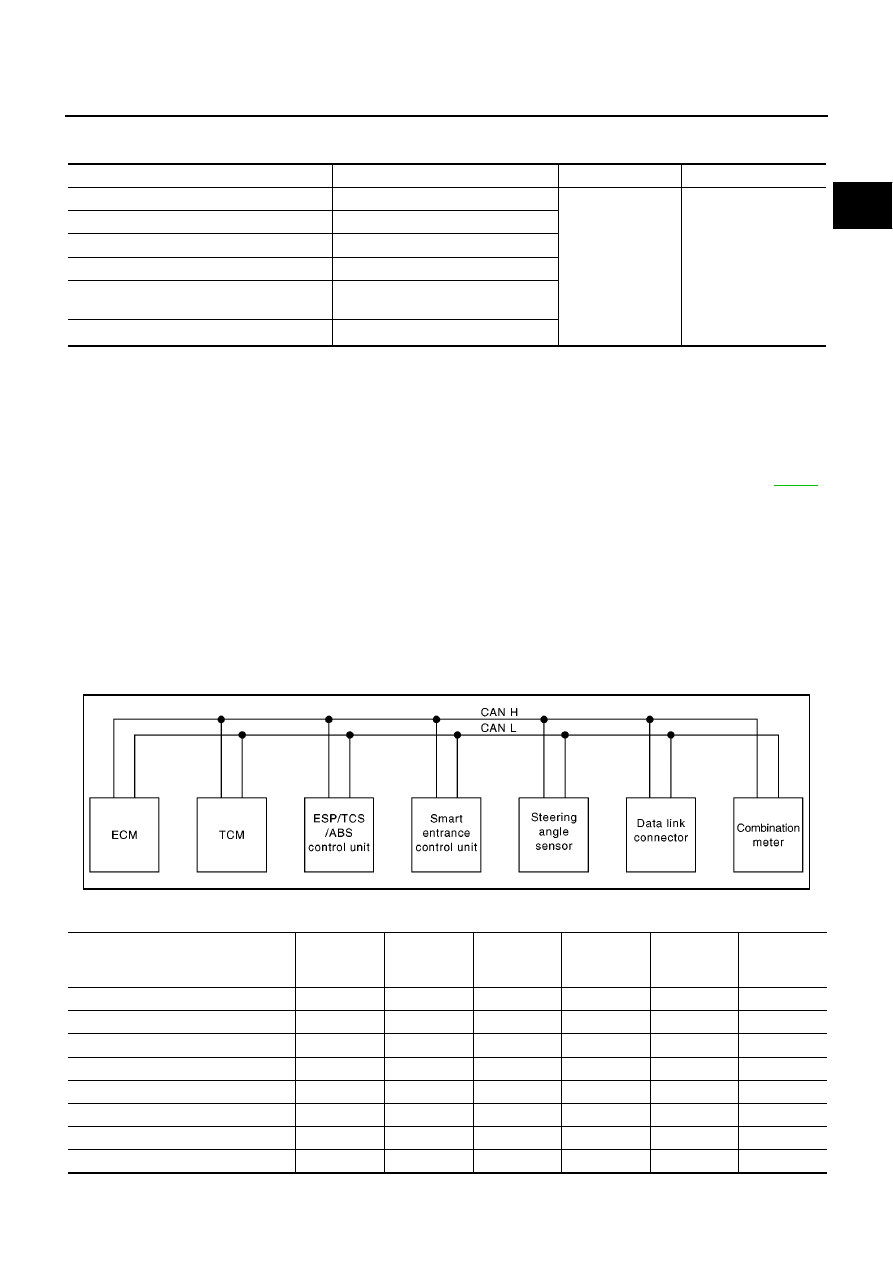
A/T MODELS WITH ESP
System diagram

Input/output signal chart

T: Transmit R: Receive

Sensor

Input Signal to ECM

ECM Function

Actuator

Park/neutral position (PNP) switch

Neutral position

Fuel cut control

Fuel injectors

Throttle position sensor

Throttle position

Accelerator pedal position sensor

Accelerator pedal position

Engine coolant temperature sensor

Engine coolant temperature

Crankshaft position sensor (POS)
Camshaft position sensor (PHASE)

Engine speed

Vehicle speed signal

*1

Vehicle speed

YEL465E

Signals

ECM

TCM

ESP/TCS/

ABS control

unit

Smart

entrance

control unit

Steering

angle sensor

Combination

meter

Engine speed signal

T

R

R

Brake switch signal

R

T

Rear window defogger signal

R

T

Heater fan switch signal

R

T

Air conditioner switch signal

R

T

MI signal

T

R

Engine coolant temperature signal

T

R

Fuel consumption signal

T

R

EC-44

[QG (WITH EURO-OBD)]

ENGINE CONTROL SYSTEM

M/T MODELS WITH ESP
System diagram

Input/output signal chart

T: Transmit R: Receive

Vehicle speed signal

T

R

R

T

Seat belt reminder signal

R

T

Headlamp switch signal

T

R

Flashing indicator signal

T

R

Engine cooling fan speed signal

T

R

Door switches state signal

T

R

A/C compressor signal

T

R

A/C compressor feedback signal

T

R

Accelerator pedal position signal

T

R

Output shaft revolution signal

R

T

OD OFF switch signal

R

T

OD OFF indicator signal

T

R

A/T self-diagnosis signal

R

T

P range signal

T

R

Steering angle sensor signal

R

T

A/T position indicator signal

R

T

R

R

ABS warning lamp signal

T

R

Slip indicator lamp signal

T

R

VDC Off indicator lamp signal

T

R

Brake warning lamp signal

T

R

N range switch signal

R

T

P range switch signal

R

T

Signals

ECM

TCM

ESP/TCS/

ABS control

unit

Smart

entrance

control unit

Steering

angle sensor

Combination

meter

YEL466E

Signals

ECM

ESP/TCS/ABS

control unit

Smart entrance

control unit

Steering angle

sensor

Combination

meter

Engine speed signal

T

R

R

Rear window defogger signal

R

T

Heater fan switch signal

R

T

Air conditioner switch signal

R

T

MI signal

T

R

Engine coolant temperature signal

T

R

ENGINE CONTROL SYSTEM

EC-45

[QG (WITH EURO-OBD)]

C

D

E

F

G

H

I

J

K

L

M

A

EC

A/T MODELS WITHOUT ESP
System diagram

Input/output signal chart

T: Transmit R: Receive

Fuel consumption signal

T

R

Vehicle speed signal

T

R

R

T

Seat belt reminder signal

R

T

Headlamp switch signal

T

R

Flashing indicator signal

T

R

Engine cooling fan speed signal

T

R

Door switches state signal

T

R

A/C compressor signal

T

R

A/C compressor feedback signal

T

R

Accelerator pedal position signal

T

R

Steering angle sensor signal

R

T

ABS warning lamp signal

T

R

Slip indicator lamp signal

T

R

VDC off indicator lamp signal

T

R

Brake warning lamp signal

T

R

Signals

ECM

ESP/TCS/ABS

control unit

Smart entrance

control unit

Steering angle

sensor

Combination

meter

YEL468E

Signals

ECM

TCM

ABS actuator

and electric

unit (control

unit)

Smart entrance

control unit

Combination

meter

Engine speed signal

T

R

Brake switch signal

R

T

Rear window defogger signal

R

T

Heater fan switch signal

R

T

Air conditioner switch signal

R

T

MI signal

T

R

Engine coolant temperature signal

T

R

Fuel consumption signal

T

R

Vehicle speed signal

T

R

R

T

Seat belt reminder signal

R

T

Headlamp switch signal

T

R

EC-46

[QG (WITH EURO-OBD)]

ENGINE CONTROL SYSTEM

M/T MODELS WITHOUT ESP
System diagram

Input/output signal chart

T: Transmit R: Receive

Flashing indicator signal

T

R

Engine cooling fan speed signal

T

R

Door switches state signal

T

R

A/C compressor signal

T

R

A/C compressor feedback signal

T

R

Accelerator pedal position signal

T

R

Output shaft revolution signal

R

T

ABS operation signal

T

R

OD OFF switch signal

R

T

OD OFF indicator signal

T

R

A/T self-diagnosis signal

R

T

ABS warning lamp signal

T

R

N range switch signal

R

T

P range switch signal

R

T

Signals

ECM

TCM

ABS actuator

and electric

unit (control

unit)

Smart entrance

control unit

Combination

meter

YEL469E

Signals

ECM

ABS actuator and

electric unit (con-

trol unit)

Smart entrance

control unit

Combination meter

Engine speed signal

T

R

Rear window defogger signal

R

T

Heater fan switch signal

R

T

Air conditioner switch signal

R

T

MI signal

T

R

Engine coolant temperature signal

T

R

Fuel consumption signal

T

R

Vehicle speed signal

T

R

R

T

Seat belt reminder signal

R

T

Headlamp switch signal

T

R

Flashing indicator signal

T

R

Engine cooling fan speed signal

T

R

Door switches state signal

T

R

ENGINE CONTROL SYSTEM

EC-47

[QG (WITH EURO-OBD)]

C

D

E

F

G

H

I

J

K

L

M

A

EC

A/C compressor signal

T

R

A/C compressor feedback signal

T

R

ABS operation signal

T

R

ABS warning lamp signal

T

R

Signals

ECM

ABS actuator and

electric unit (con-

trol unit)

Smart entrance

control unit

Combination meter

EC-48

[QG (WITH EURO-OBD)]

BASIC SERVICE PROCEDURE

BASIC SERVICE PROCEDURE

PFP:00018

Idle Speed and Ignition Timing Check

EBS00QGK

IDLE SPEED

With CONSULT-II

Check idle speed in “DATA MONITOR” mode with CONSULT-II.

With GST

Check idle speed in with GST.

IGNITION TIMING

Any of following two methods may be used.

Method A

1.

Slide the harness protector of ignition coil No. 1 to clear the wires.

2.

Attach timing light to the wires as shown.

3.

Check ignition timing.

Method B

1.

Remove No. 1 ignition coil.

SEF058Y

MBIB0047E

MBIB0048E

BASIC SERVICE PROCEDURE

EC-49

[QG (WITH EURO-OBD)]

C

D

E

F

G

H

I

J

K

L

M

A

EC

2.

Connect No. 1 ignition coil and No. 1 spark plug with suitable
high-tension wire as shown, and attach timing light clamp to this
wire.

3.

Check ignition timing.

Accelerator Pedal Released Position Learning

EBS00QGL

DESCRIPTION

“Accelerator Pedal Released Position Learning” is an operation to learn the fully released position of the accel-
erator pedal by monitoring the accelerator pedal position sensor output signal. It must be performed each time
harness connector of accelerator pedal position sensor or ECM is disconnected.

OPERATION PROCEDURE

1.

Make sure that accelerator pedal is fully released.

2.

Turn ignition switch “ON” and wait at least 2 seconds.

3.

Turn ignition switch “OFF” wait at least 10 seconds.

4.

Turn ignition switch “ON” and wait at least 2 seconds.

5.

Turn ignition switch “OFF” wait at least 10 seconds.

Throttle Valve Closed Position Learning

EBS00QGM

DESCRIPTION

“Throttle Valve Closed Position Learning” is an operation to learn the fully closed position of the throttle valve
by monitoring the throttle position sensor output signal. It must be performed each time harness connector of
electric throttle control actuator or ECM is disconnected.

OPERATION PROCEDURE

1.

Make sure that accelerator pedal is fully released.

2.

Turn ignition switch “ON”.

3.

Turn ignition switch “OFF” wait at least 10 seconds.
Make sure that throttle valve moves during above 10 seconds by confirming the operating sound.

Idle Air Volume Learning

EBS00QGN

DESCRIPTION

“Idle Air Volume Learning” is an operation to learn the idle air volume that keeps each engine within the spe-
cific range. It must be performed under any of the following conditions:

Each time electric throttle control actuator or ECM is replaced.

Idle speed or ignition timing is out of specification.

MBIB0049E

SEF166Y

EC-50

[QG (WITH EURO-OBD)]

BASIC SERVICE PROCEDURE

PREPARATION

Before performing “Idle Air Volume Learning”, make sure that all of the following conditions are satisfied.
Learning will be cancelled if any of the following conditions are missed for even a moment.

Battery voltage: More than 12.9V (At idle)

Engine coolant temperature: 70 - 95

°

C (158 - 203

°

F)

PNP switch: ON

Electric load switch: OFF
(Air conditioner, headlamp, rear window defogger)
On vehicles equipped with daytime light systems, set lighting switch to the 1st position to light
only small lamps.

Steering wheel: Neutral (Straight-ahead position)

Vehicle speed: Stopped

Transmission: Warmed-up
For models with CONSULT-II, drive vehicle until “FLUID TEMP SE” in “DATA MONITOR” mode of “A/T”
system indicates less than 0.9V.
For models without CONSULT-II, drive vehicle for 10 minutes.

OPERATION PROCEDURE

With CONSULT-II

1.

Perform

EC-49, "Accelerator Pedal Released Position Learning"

.

2.

Perform

EC-49, "Throttle Valve Closed Position Learning"

.

3.

Start engine and warm it up to normal operating temperature.

4.

Check that all items listed under the topic “PREPARATION” (previously mentioned) are in good order.

5.

Select “IDLE AIR VOL LEARN” in “WORK SUPPORT” mode.

6.

Touch “START” and wait 20 seconds.

SEF217Z

SEF454Y

BASIC SERVICE PROCEDURE

EC-51

[QG (WITH EURO-OBD)]

C

D

E

F

G

H

I

J

K

L

M

A

EC

7.

Make sure that “CMPLT” is displayed on CONSULT-II screen. If
“CMPLT” is not displayed, “Idle Air Volume Learning” will not be
carried out successfully. In this case, find the cause of the inci-
dent by referring to the “Diagnostic Procedure” below.

8.

Rev up the engine two or three times and make sure that idle
speed and ignition timing are within the specifications.

Without CONSULT-II

NOTE:

It is better to count the time accurately with a clock.

It is impossible to switch the diagnostic mode when an accelerator pedal position sensor circuit
has a malfunction.

1.

Perform

EC-49, "Accelerator Pedal Released Position Learning"

.

2.

Perform

EC-49, "Throttle Valve Closed Position Learning"

.

3.

Start engine and warm it up to normal operating temperature.

4.

Check that all items listed under the topic “PREPARATION” (previously mentioned) are in good order.

5.

Turn ignition switch “OFF” and wait at least 10 seconds.

6.

Confirm that accelerator pedal is fully released, turn ignition switch “ON” and wait 3 seconds.

7.

Repeat the following procedure quickly five times within 5 seconds.

a.

Fully depress the accelerator pedal.

b.

Fully release the accelerator pedal.

8.

Wait 7 seconds, fully depress the accelerator pedal and keep it for approx. 20 seconds until the MI stops
blinking and turned ON.

9.

Fully release the accelerator pedal within 3 seconds after the MI turned ON.

10. Start engine and let it idle.

11. Wait 20 seconds.

12. Rev up the engine two or three times and make sure that idle speed and ignition timing are within the

specifications.

13. If idle speed and ignition timing are not within the specification, “Idle Air Volume Learning” will not be car-

ried out successfully. In this case, find the cause of the incident by referring to the “Diagnostic Procedure”
below.

ITEM

SPECIFICATION

Idle speed

M/T: 700

±

50 rpm (in “Neutral” position)

A/T: 800

±

50 rpm (in “P” or “N” position)

Ignition timing

M/T: 8

±

5

°

BTDC (in “Neutral” position)

A/T: 10

±

5

°

BTDC (in “P” or “N” position)

MBIB0238E

ITEM

SPECIFICATION

Idle speed

M/T: 700

±

50 rpm (in “Neutral” position)

A/T: 800

±

50 rpm (in “P” or “N” position)

Ignition timing

M/T: 8

±

5

°

BTDC (in “Neutral” position)

A/T: 10

±

5

°

BTDC (in “P” or “N” position)

PBIB0665E

EC-52

[QG (WITH EURO-OBD)]

BASIC SERVICE PROCEDURE

DIAGNOSTIC PROCEDURE

If idle air volume learning cannot be performed successfully, proceed as follows:

1.

Check that throttle valve is fully closed.

2.

Check PCV valve operation.

3.

Check that downstream of throttle valve is free from air leakage.

4.

When the above three items check out OK, engine component parts and their installation condi-
tion are questionable. Check and eliminate the cause of the incident.
It is useful to perform

EC-134, "TROUBLE DIAGNOSIS - SPECIFICATION VALUE"

.

5.

If any of the following conditions occur after the engine has started, eliminate the cause of the
incident and perform “Idle air volume learning” all over again:

Engine stalls.

Erroneous idle.

Fuel Pressure Check

EBS00QGO

FUEL PRESSURE RELEASE

Before disconnecting fuel line, release fuel pressure from fuel line to eliminate danger.

NOTE:
Prepare pans or saucers under the disconnected fuel line because the fuel may spill out. The fuel pres-
sure cannot be completely released because V10 models do not have fuel return system.

With CONSULT-II

1.

Turn ignition switch “ON”.

2.

Perform “FUEL PRESSURE RELEASE” in “WORK SUPPORT”
mode with CONSULT-II.

3.

Start engine.

4.

After engine stalls, crank it two or three times to release all fuel
pressure.

5.

Turn ignition switch “OFF”.

Without CONSULT-II

1.

Remove fuel pump fuse located in fuse box.

2.

Start engine.

3.

After engine stalls, crank it two or three times to release all fuel
pressure.

4.

Turn ignition switch “OFF”.

5.

Reinstall fuel pump fuse after servicing fuel system.

FUEL PRESSURE CHECK

NOTE:

When reconnecting fuel line, always use new clamps.

Make sure that clamp screw does not contact adjacent parts.

Use a torque driver to tighten clamps.

Use Pressure Gauge to check fuel pressure.

1.

Release fuel pressure to zero. Refer to

EC-52, "FUEL PRESSURE RELEASE"

.

SEF214Y

MBIB0999E

BASIC SERVICE PROCEDURE

EC-53

[QG (WITH EURO-OBD)]

C

D

E

F

G

H

I

J

K

L

M

A

EC

2.

Install the fuel pressure gauge into the fuel line as shown in the
figure.

3.

Turn ignition switch “ON”, and check for fuel leakage.

4.

Start engine and check for fuel leakage.

5.

Read the indication of fuel pressure gauge.

6.

If result is unsatisfactory, go to next step.

7.

Check the following.

Fuel hoses and fuel tubes for clogging

Fuel filter for clogging

Fuel pump

Fuel pressure regulator for clogging

If OK, replace fuel pressure regulator.
If NG, repair or replace.

At idling:

Approximately 350 kPa (3.5 bar, 3.57 kg/cm

2

, 51 psi)

MBIB0050E

EC-54

[QG (WITH EURO-OBD)]

ON BOARD DIAGNOSTIC (OBD) SYSTEM

ON BOARD DIAGNOSTIC (OBD) SYSTEM

PFP:00028

Introduction

EBS00QGP

The ECM has an on board diagnostic system, which detects malfunctions related to engine sensors or actua-
tors. The ECM also records various emission-related diagnostic information including:

The above information can be checked using procedures listed in the table below.

×

: Applicable

—: Not applicable

*1: 1st trip DTCs for self-diagnoses concerning SRT items cannot be shown on the GST display.
*2: When DTC and 1st trip DTC simultaneously appear on the display, they cannot be clearly distinguished from each other.

The malfunction indicator (MI) on the instrument panel lights up when the same malfunction is detected in two
consecutive trips (Two trip detection logic), or when the ECM enters fail-safe mode. (Refer to

EC-85

.)

Two Trip Detection Logic

EBS00QGQ

When a malfunction is detected for the first time, 1st trip DTC and 1st trip Freeze Frame data are stored in the
ECM memory. The MI will not light up at this stage. <1st trip>
If the same malfunction is detected again during the next drive, the DTC and Freeze Frame data are stored in
the ECM memory, and the MI lights up. The MI lights up at the same time when the DTC is stored. <2nd trip>
The “trip” in the “Two Trip Detection Logic” means a driving mode in which self-diagnosis is performed during
vehicle operation. Specific on board diagnostic items will cause the ECM to light up or blink the MI, and store
DTC and Freeze Frame data, even in the 1st trip, as shown below.

×

: Applicable

—: Not applicable

When there is an open circuit on MI circuit, the ECM can not warn the driver by lighting up MI when there is
malfunction on engine control system.
Therefore, when electrical controlled throttle and part of ECM related diagnoses are continuously detected as
NG for 5 trips, ECM warns the driver that engine control system has trouble and MI circuit is open by means of
operating fail-safe function.

Emission-related diagnostic information

ISO Standard

Diagnostic Trouble Code (DTC)

Mode 3 of ISO 15031-5

Freeze Frame data

Mode 2 of ISO 15031-5

System Readiness Test (SRT) code

Mode 1 of ISO 15031-5

1st Trip Diagnostic Trouble Code (1st Trip DTC)

Mode 7 of ISO 15031-5

1st Trip Freeze Frame data

Test values and Test limits

Mode 6 of ISO 15031-5

Calibration ID

Mode 9 of ISO 15031-5

DTC

1st trip DTC

Freeze Frame

data

1st trip Freeze

Frame data

SRT code

Test value

CONSULT-II

×

×

×

×

×

GST

×

×

*

1

×

×

×

ECM

×

×

*

2

Items

MI

DTC

1st trip DTC

1st trip

2nd trip

1st trip

displaying

2nd trip

displaying

1st trip

displaying

2nd trip

display-

ing

Blinking

Lighting

up

Blinking

Lighting

up

Misfire (Possible three way cata-
lyst damage) — DTC: P0300 -
P0304 is being detected

×

×

Misfire (Possible three way cata-
lyst damage) — DTC: P0300 -
P0304 is being detected

×

×

One trip detection diagnoses
(Refer to

EC-20

.)

×

×

×

Except above

×

×

×

ON BOARD DIAGNOSTIC (OBD) SYSTEM

EC-55

[QG (WITH EURO-OBD)]

C

D

E

F

G

H

I

J

K

L

M

A

EC

The fail-safe function also operate when above diagnoses except MI circuit are detected and demands the
driver to repair the trouble.

Emission-related Diagnostic Information

EBS00QGR

EMISSION-RELATED DIAGNOSTIC INFORMATION ITEMS
M/T Models

Engine operating condition in fail-safe mode

Engine speed will not rise more than 2,500 rpm due to the fuel cut

Items

(CONSULT-II screen terms)

DTC*

1

SRT code

Test Value/

Test Limit

(GST only)

1st trip DTC

Reference page

CONSULT-II

GST*

2

ECM

CAN COMM CIRCUIT

U1001

1001*

3

×

EC-145

NO DTC IS DETECTED.
FURTHER TESTING
MAY BE REQUIRED.

P0000

0000

INT/V TIM CONT-B1

P0011

0011

×

EC-148

HO2S1 HTR (B1)

P0031

0031

×

×

×

*

4

EC-151

HO2S1 HTR (B1)

P0032

0032

×

×

×

*

4

EC-151

HO2S2 HTR (B1)

P0037

0037

×

×

×

*

4

EC-165

HO2S2 HTR (B1)

P0038

0038

×

×

×

*

4

EC-165

MAF SEN/CIRCUIT

P0102

0102

EC-178

MAF SEN/CIRCUIT

P0103

0103

EC-178

IAT SEN/CIRCUIT

P0112

0112

×

EC-184

IAT SEN/CIRCUIT

P0113

0113

×

EC-184

ECT SEN/CIRCUIT

P0117

0117

EC-188

ECT SEN/CIRCUIT

P0118

0118

EC-188

HO2S1 (B1)

P0132

0132

×

×

×

*

4

EC-193

HO2S1 (B1)

P0133

0133

×

×

×

*

4

EC-208

HO2S1 (B1)

P0134

0134

×

×

×

*

4

EC-230

HO2S2 (B1)

P0138

0138

×

×

×

*

4

EC-247

HO2S2 (B1)

P0139

0139

×

×

×

*

4

EC-262

FUEL SYS-LEAN-B1

P0171

0171

×

EC-281

FUEL SYS-RICH-B1

P0172

0172

×

EC-296

TP SENSOR

P0221

0221

EC-310

TP SEN 1/CIRC

P0222

0222

EC-316

TP SEN 1/CIRC

P0223

0223

EC-316

APP SENSOR

P0226

0226

EC-322

APP SEN 1/CIRC

P0227

0227

EC-328

APP SEN 1/CIRC

P0228

0228

EC-328

MULTI CYL MISFIRE

P0300

0300

×

EC-334

CYL 1 MISFIRE

P0301

0301

×

EC-334

CYL 2 MISFIRE

P0302

0302

×

EC-334

CYL 3 MISFIRE

P0303

0303

×

EC-334

CYL 4 MISFIRE

P0304

0304

×

EC-334

KNOCK SEN/CIRC-B1

P0327

0327

×

EC-339

KNOCK SEN/CIRC-B1

P0328

0328

×

EC-339

CKP SEN/CIRCUIT

P0335

0335

×

EC-343

EC-56

[QG (WITH EURO-OBD)]

ON BOARD DIAGNOSTIC (OBD) SYSTEM

*1: 1st trip DTC No. is the same as DTC No.
*2: These numbers are prescribed by ISO 15031-5.
*3: The trouble shooting for this DTC needs CONSULT-II.
*4: These are not displayed with GST.

A/T Models

CMP SEN/CIRC-B1

P0340

0340

×

EC-349

TW CATALYST SYS-B1

P0420

0420

×

×

×

*

4

EC-355

PURG VOLUME CONT/V

P0444

0444

×

EC-365

VEH SPEED SEN/CIRC

P0500

0500

×

EC-371

PW ST P SEN/CIRC

P0550

0550

×

EC-373

ECM

P0605

0605

×

EC-377

ECM BACK UP/CIRC

P1065

1065

×

EC-380

INT/V TIM V/CIR-B1

P1111

1111

×

EC-384

ETC ACTR

P1121

1121

×

EC-389

ETC FUNCTION/CIRC

P1122

1122

EC-391

ETC MOT PWR

P1124

1124

EC-398

ETC MOT PWR

P1126

1126

EC-398

ETC MOT

P1128

1128

EC-404

HO2S1 (B1)

P1143

1143

×

×

×

*

4

EC-409

HO2S1 (B1)

P1144

1144

×

×

×

*

4

EC-421

HO2S2 (B1)

P1146

1146

×

×

×

*

4

EC-433

HO2S2 (B1)

P1147

1147

×

×

×

*

4

EC-452

TCS C/U FUNCTN

P1211

1211

×

EC-471

TCS/CIRC

P1212

1212

×

EC-472

ENG OVER TEMP

P1217

1217

EC-473

TP SEN 2/CIRC

P1223

1223

EC-484

TP SEN 2/CIRC

P1224

1224

EC-484

CTP LEARNING

P1225

1225

×

EC-490

CTP LEARNING

P1226

1226

×

EC-492

APP SEN 2/CIRC

P1227

1227

EC-494

APP SEN 2/CIRC

P1228

1228

EC-494

SENSOR POWER/CIRC

P1229

1229

EC-500

NATS MALFUNCTION

P1610 - P1615

1610 - 1615

×

EC-70

P-N POS SW/CIRCUIT

P1706

1706

×

EC-504

BRAKE SW/CIRCUIT

P1805

1805

×

EC-509

Items

(CONSULT-II screen terms)

DTC*

1

SRT code

Test Value/

Test Limit

(GST only)

1st trip DTC

Reference page

CONSULT-II

GST*

2

ECM

Items

(CONSULT-II screen terms)

DTC*

1

SRT code

Test Value/

Test Limit

(GST only)

1st trip DTC

Reference page

CONSULT-II

GST*

2

ECM

CAN COMM CIRCUIT

U1000

1000*

3

EC-145

CAN COMM CIRCUIT

U1001

1001*

3

×

EC-145

NO DTC IS DETECTED.
FURTHER TESTING
MAY BE REQUIRED.

P0000

0000

ON BOARD DIAGNOSTIC (OBD) SYSTEM

EC-57

[QG (WITH EURO-OBD)]

C

D

E

F

G

H

I

J

K

L

M

A

EC

INT/V TIM CONT-B1

P0011

0011

×

EC-148

HO2S1 HTR (B1)

P0031

0031

×

×

×

*

4

EC-157

HO2S1 HTR (B1)

P0032

0032

×

×

×

*

4

EC-157

HO2S2 HTR (B1)

P0037

0037

×

×

×

*

4

EC-170

HO2S2 HTR (B1)

P0038

0038

×

×

×

*

4

EC-170

HO2S1 HTR (B2)

P0051

0051

×

×

×

*

4

EC-157

HO2S1 HTR (B2)

P0052

0052

×

×

×

*

4

EC-157

HO2S2 HTR (B2)

P0057

0057

×

×

×

*

4

EC-170

HO2S2 HTR (B2)

P0058

0058

×

×

×

*

4

EC-170

MAF SEN/CIRCUIT

P0102

0102

EC-178

MAF SEN/CIRCUIT

P0103

0103

EC-178

IAT SEN/CIRCUIT

P0112

0112

×

EC-184

IAT SEN/CIRCUIT

P0113

0113

×

EC-184

ECT SEN/CIRCUIT

P0117

0117

EC-188

ECT SEN/CIRCUIT

P0118

0118

EC-188

HO2S1 (B1)

P0132

0132

×

×

×

*

4

EC-199

HO2S1 (B1)

P0133

0133

×

×

×

*

4

EC-218

HO2S1 (B1)

P0134

0134

×

×

×

*

4

EC-237

HO2S2 (B1)

P0138

0138

×

×

×

*

4

EC-253

HO2S2 (B1)

P0139

0139

×

×

×

*

4

EC-270

HO2S1 (B2)

P0152

0152

×

×

×

*

4

EC-199

HO2S1 (B2)

P0153

0153

×

×

×

*

4

EC-218

HO2S1 (B2)

P0154

0154

×

×

×

*

4

EC-237

HO2S2 (B2)

P0158

0158

×

×

×

*

4

EC-253

HO2S2 (B2)

P0159

0159

×

×

×

*

4

EC-270

FUEL SYS-LEAN-B1

P0171

0171

×

EC-288

FUEL SYS-RICH-B1

P0172

0172

×

EC-302

FUEL SYS-LEAN-B2

P0174

0174

×

EC-288

FUEL SYS-RICH-B2

P0175

0175

×

EC-302

TP SENSOR

P0221

0221

EC-310

TP SEN 1/CIRC

P0222

0222

EC-316

TP SEN 1/CIRC

P0223

0223

EC-316

APP SENSOR

P0226

0226

EC-322

APP SEN 1/CIRC

P0227

0227

EC-328

APP SEN 1/CIRC

P0228

0228

EC-328

MULTI CYL MISFIRE

P0300

0300

×

EC-334

CYL 1 MISFIRE

P0301

0301

×

EC-334

CYL 2 MISFIRE

P0302

0302

×

EC-334

CYL 3 MISFIRE

P0303

0303

×

EC-334

CYL 4 MISFIRE

P0304

0304

×

EC-334

Items

(CONSULT-II screen terms)

DTC*

1

SRT code

Test Value/

Test Limit

(GST only)

1st trip DTC

Reference page

CONSULT-II

GST*

2

ECM

EC-58

[QG (WITH EURO-OBD)]

ON BOARD DIAGNOSTIC (OBD) SYSTEM

KNOCK SEN/CIRC-B1

P0327

0327

×

EC-339

KNOCK SEN/CIRC-B1

P0328

0328

×

EC-339

CKP SEN/CIRCUIT

P0335

0335

×

EC-343

CMP SEN/CIRC-B1

P0340

0340

×

EC-349

TW CATALYST SYS-B1

P0420

0420

×

×

×

*

4

EC-360

TW CATALYST SYS-B2

P0430

0430

×

×

×

*

4

EC-360

PURG VOLUME CONT/V

P0444

0444

×

EC-365

VEH SPEED SEN/CIRC*

5

P0500

0500

×

EC-371

PW ST P SEN/CIRC

P0550

0550

×

EC-373

ECM

P0605

0605

×

EC-377

PNP SW/CIRC

P0705

0705

×

AT-113

ATF TEMP SEN/CIRC

P0710

0710

×

AT-119

VEH SPD SEN/CIRC AT*

5

P0720

0720

×

AT-125

ENGINE SPEED SIG

P0725

0725

×

AT-131

A/T 1ST GR FNCTN

P0731

0731

×

AT-135

A/T 2ND GR FNCTN

P0732

0732

×

AT-141

A/T 3RD GR FNCTN

P0733

0733

×

AT-147

A/T 4TH GR FNCTN

P0734

0734

×

AT-153

TCC SOLENOID/CIRC

P0740

0740

×

AT-161

L/PRESS SOL/CIRC

P0745

0745

×

AT-166

SFT SOL A/CIRC

P0750

0750

AT-173

SFT SOL B/CIRC

P0755

0755

AT-178

ECM BACK UP/CIRC

P1065

1065

×

EC-380

INT/V TIM V/CIR-B1

P1111

1111

×

EC-384

ETC ACTR

P1121

1121

×

EC-389

ETC FUNCTION/CIRC

P1122

1122

EC-391

ETC MOT PWR

P1124

1124

EC-398

ETC MOT PWR

P1126

1126

EC-398

ETC MOT

P1128

1128

EC-404

HO2S1 (B1)

P1143

1143

×

×

×

*

4

EC-415

HO2S1 (B1)

P1144

1144

×

×

×

*

4

EC-427

HO2S2 (B1)

P1146

1146

×

×

×

*

4

EC-441

HO2S2 (B1)

P1147

1147

×

×

×

*

4

EC-460

HO2S1 (B2)

P1163

1163

×

×

×

*

4

EC-415

HO2S1 (B2)

P1164

1164

×

×

×

*

4

EC-427

HO2S2 (B2)

P1166

1166

×

×

×

*

4

EC-441

HO2S2 (B2)

P1167

1167

×

×

×

*

4

EC-460

TCS C/U FUNCTN

P1211

1211

×

EC-471

TCS/CIRC

P1212

1212

×

EC-472

ENG OVER TEMP

P1217

1217

EC-473

TP SEN 2/CIRC

P1223

1223

EC-484

Items

(CONSULT-II screen terms)

DTC*

1

SRT code

Test Value/

Test Limit

(GST only)

1st trip DTC

Reference page

CONSULT-II

GST*

2

ECM


Content      ..     62      63      64      65     ..